A dust trolley with synchronous steering of the mop

A technology of dust carts and mops, which is applied in the field of dust carts and can solve the problems of large size and inability to turn the mop synchronously

Active Publication Date: 2020-08-14
JIANGSU JINPENG GRP CO LTD
View PDF6 Cites 0 Cited by
  • Summary
  • Abstract
  • Description
  • Claims
  • Application Information

AI Technical Summary

Problems solved by technology

[0004] The invention provides a dust trolley whose mop can be turned synchronously, which can solve the problems in the prior art that the dust trolley is relatively large and the mop cannot be turned synchronously

Method used


Image

  • A dust trolley with synchronous steering of the mop
  • A dust trolley with synchronous steering of the mop
  • A dust trolley with synchronous steering of the mop

Examples


Embodiment 1

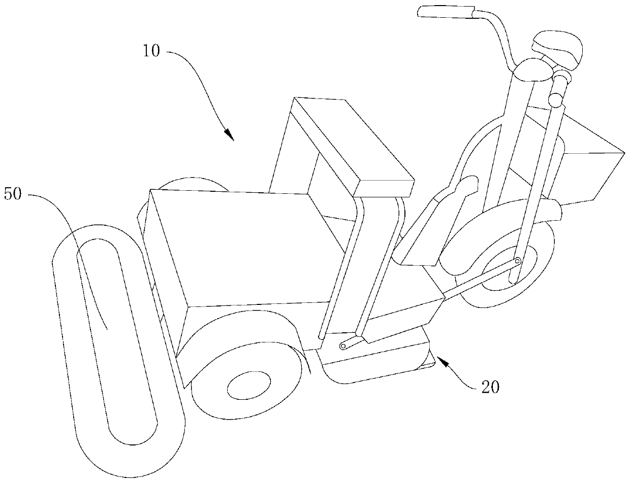
[0034] Such as figure 1 Shown, comprise car body 10 and cleaning mop 20, car body 10 has a front wheel, and front wheel is installed on the front fork, also comprises two connecting rods, is positioned at the both sides of front wheel respectively, and one end of connecting rod is hinged on On the cleaning mop 20, the other end is hinged on the front fork, when the front fork rotates, it drives the connecting rod, and the connecting rod drives the cleaning mop 20 to rotate synchronously.

Embodiment 2

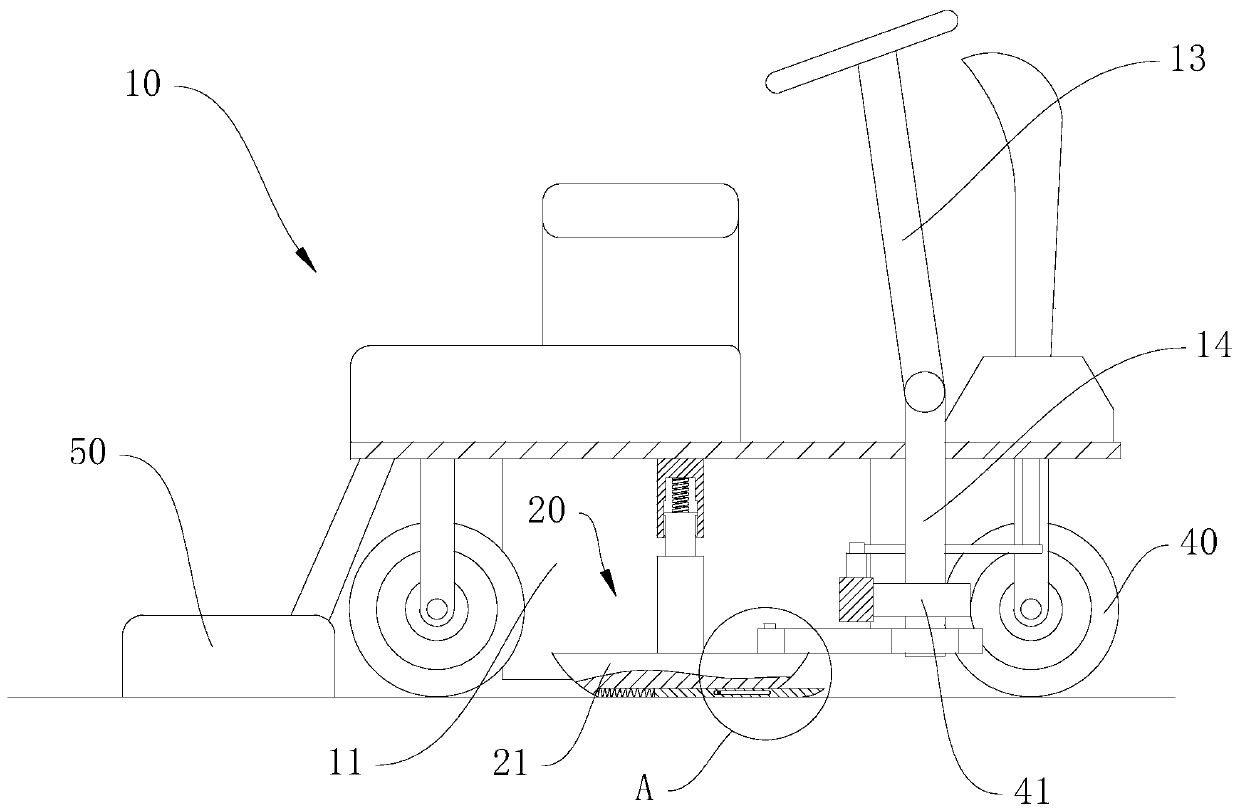
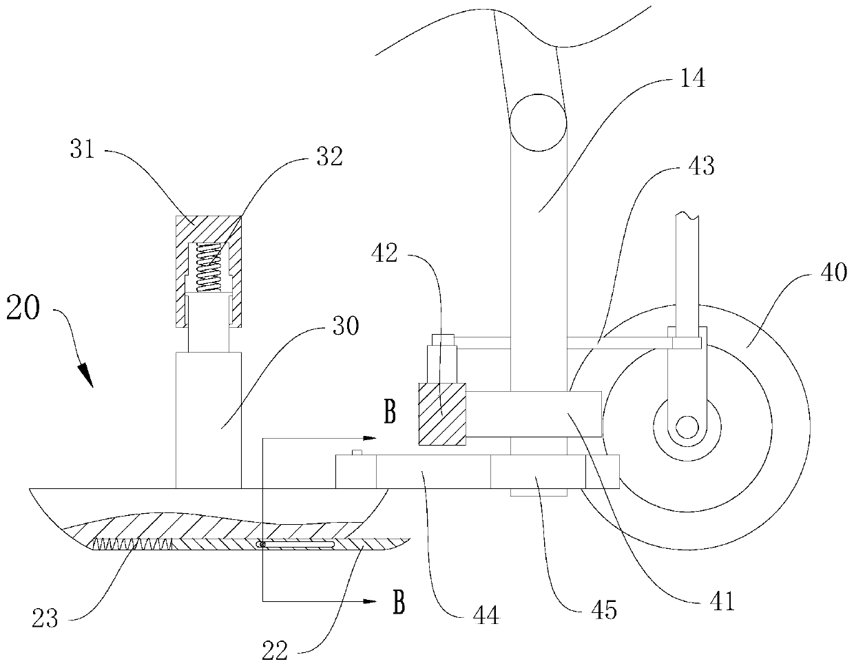
[0036] Such as Figure 2 to Figure 10 As shown, the embodiment of the present invention provides a mop synchronously steerable dust trolley, including a car body 10 and a cleaning mop 20, the car body 10 has a steering wheel 12, a first steering shaft 13 connected to the steering wheel 12 and The second steering shaft 14, the first steering shaft 13 is rotatably arranged on the vehicle body 10, this part is the same as the steering gear in the prior art, and one end of the first steering shaft 13 is connected to the second steering shaft 13 through a universal joint. The other end of the steering shaft 14, the second steering shaft 14 is rotatably arranged on the car body 10, and also includes a synchronous steering device, and the cleaning mop 20 is rotatably arranged on the car body 10 through a support rod 30;

[0037] The synchronous steering device includes a steering gear 41 coaxially arranged on the second steering shaft 14, a synchronous gear 45 coaxially arranged on t...


PUM


Abstract

The invention discloses a dust cart with a mop synchronous rotation function, and belongs to the field of cleaning devices. The dust cart comprises a cart body, a cleaning mop and a synchronous rotation device, wherein the cart body is provided with a steering wheel, a first steering shaft and a second steering shaft, and the first steering shaft and the second steering shaft are connected with the steering wheel; the cleaning mop is rotationally arranged on the cart body through a support rod; the synchronous rotation device comprises a steering gear, a synchronous gear, a steering gear rack,a steering connecting rod and synchronous gear racks in a coaxial way, the steering gear is arranged on the second steering shaft, the synchronous gear is synchronously arranged on the second steering shaft, the steering gear rack is glidingly arranged on the cart body, the steering connecting rod is positioned at both sides of the steering gear, and the synchronous gear racks are positioned at both sides of the steering gear; one end of the steering connecting rod is hinged to the steering gear rack, and the other end of the steering connecting rod is fixedly connected with a front wheel ofthe cart body; the synchronous gear racks are glidingly arranged on the cart body, and one end of each synchronous gear rack is hinged to the cleaning mop. The dust cart has the advantages that the function of synchronous steering of the mop and the front wheel is realized, and the direction of the mop can be changed at smaller steering radius.

Description

technical field [0001] The invention relates to the field of cleaning appliances, in particular to a dust trolley with synchronous steering of the mop. Background technique [0002] The dust trolley is the product of the combination of manual dust pusher and electric car. It makes the original manual work attached to the electric car as the carrier to realize automation. It saves manpower and improves work efficiency. Make the scope of single-person control larger. It is widely used in large supermarkets, shopping malls, airport waiting halls, stations, various workshops, warehouses and other places with heavy cleaning tasks. [0003] Existing dust carts generally have a car body, a front mop and a rear mop, but when the mop is arranged at the front end and the rear end, the car body is bulky and occupies a large area. In addition, when the vehicle is turning, the mop is often still moving in the original direction under the usual action. It needs to rely on the movement o...

Claims


Application Information

Patent Timeline
Patent Type & Authority Patents(China)
IPC IPC(8): A47L11/26A47L11/40
CPCA47L11/26A47L11/40A47L11/4036A47L11/4072
Inventor 鹿世敏朱红军
Owner JIANGSU JINPENG GRP CO LTD
Why Eureka
Try Eureka