Turning-around device for concrete wet-spraying machine cockpit

A U-turn device and cockpit technology, used in shaft equipment, earth-moving, transportation and packaging, etc., can solve the problems of difficult U-turn, hidden safety hazards, obstructing the driver's sight, etc., and achieve the effect of wide driving vision

Inactive Publication Date: 2017-04-26
FUJIAN FANGZHENG MACHINERY CO LTD
View PDF10 Cites 0 Cited by
  • Summary
  • Abstract
  • Description
  • Claims
  • Application Information

AI Technical Summary

Problems solved by technology

The concrete wet spraying machine is widely used in the initial support of the tunnel. In order to solve the problem that the wet spraying machine is difficult to turn around in the tunnel, it has appeared in the prior art to rotate the cockpit of the wet spraying machine 180° in situ or by turning the driving The seat and control parts in the cabin are rotated 180° in situ, so that the direction the driver in the cockpit is facing is rotated 180°, so as to facilitate the control of the wet jet machine to move forward or backward, but the existing in situ rotation method still exists The following problems: the cockpit is generally located at one end or in the middle of the frame, and there is a large part between the cockpit and the frame that will hinder the driver's sight, posing a great safety hazard

Method used


Image

  • Turning-around device for concrete wet-spraying machine cockpit
  • Turning-around device for concrete wet-spraying machine cockpit
  • Turning-around device for concrete wet-spraying machine cockpit

Examples


Embodiment 1

[0022] Embodiment 1: as Figure 4 As shown, the drive system 5 includes a worm gear 51, a worm screw 52 and a motor 53, the worm gear 51 is fixed on the lower end of the swing arm 4, the worm screw 52 is fixed on the output shaft of the motor 53, and the worm screw 52 meshes with the worm gear 51. The motor 53 drives the worm 52 to rotate, and the worm 52 drives the worm wheel 51 to rotate so as to drive the swing arm 4 to rotate.

Embodiment 2

[0023] Embodiment 2: as Figure 5 As shown, the drive system 5 includes a driving gear 51, a driven gear 52 and a motor (not shown), the driven gear 52 is fixed on the lower end of the swing arm 4, the driving gear 51 is fixed on the output shaft of the motor, and The driving gear 51 meshes with the driven gear 52 . The motor drives the driving gear 51 to rotate, and the driving gear 51 drives the driven gear 52 to rotate so as to drive the swing arm 4 to rotate.

Embodiment 3

[0024] Embodiment 3: as Figure 6 or Figure 7 As shown, the driving system 5 includes a slewing bearing 51, a rack 52 and a drive cylinder 53, the inner ring of the slewing bearing 51 is fixed on the vehicle frame 1, the lower end of the swing arm 4 is fixedly connected with the outer ring of the slewing bearing 51, and the driving cylinder 53 The output end of the rack is connected with the rack 52 and drives the rack 52 to move back and forth, and the rack 52 meshes with the transmission teeth of the outer ring of the slewing bearing 51 . The driving cylinder 53 drives the rack 52 to move, and the rack 52 drives the outer ring of the slewing bearing 51 to rotate so as to drive the arm to rotate.

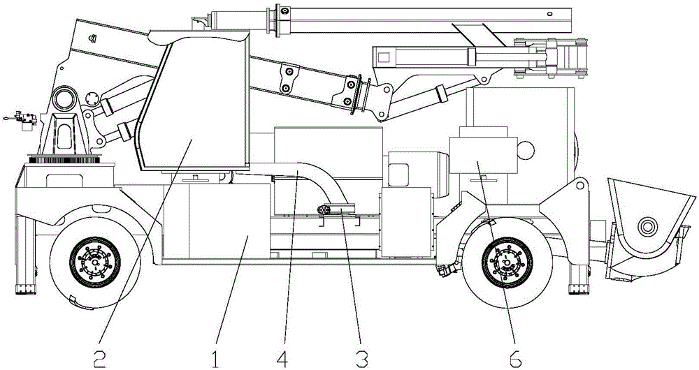
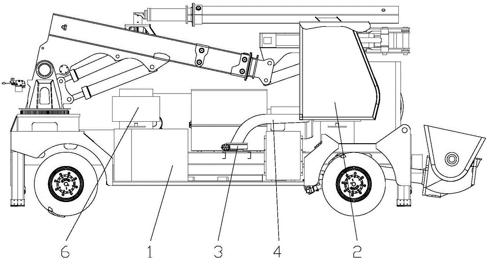
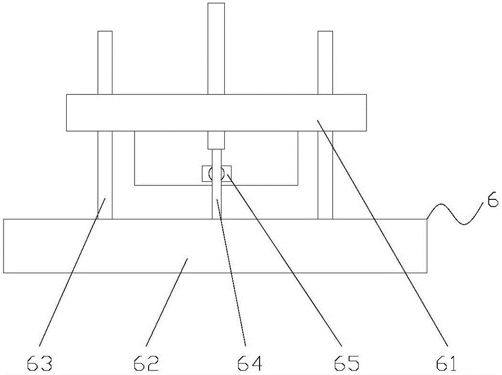
[0025] In addition, the two ends of the vehicle frame 1 and the working position of the cockpit 2 are respectively provided with buffer mechanisms 6 in place, such as image 3 As shown, the buffer mechanism 6 in place includes a base 61, a buffer plate 62, a guide rod 63, a buff...


PUM


Abstract

The invention discloses a turning-around device for a concrete wet-spraying machine cockpit, and the device comprises a vehicle frame, a cockpit, a rotating seat, and a swing arm. The rotating seat is disposed at the central part of the vehicle frame. The upper end of the swing arm is fixedly connected with the cockpit, and the lower end of the swing arm is rotatingly connected to the rotating seat. Moreover, the swing arm is driven by one drive system to rotate 180 degrees in a reciprocating manner, and the swing arm drives the cockpit to move from one end of the vehicle frame to the other end of the vehicle frame, and achieves a turning-around purpose. According to the invention, the swing arm is driven to rotate 180 degrees, thereby driving the cockpit to move from one end of a concrete wet-spraying machine to the other end of the concrete wet-spraying machine, and achieving the turning-around of the cockpit. Therefore, compared with the prior art, the device can provide a wide driving view field for a driver, and brings convenience and safety to the driver.

Description

technical field [0001] The invention relates to the field of concrete wet spraying machines, in particular to a U-turn device for a cockpit of a concrete wet spraying machine. Background technique [0002] In the construction of tunnels and underground projects, shotcrete is usually used for initial support of excavated caverns. The concrete wet spraying machine is widely used in the initial support of the tunnel. In order to solve the problem that the wet spraying machine is difficult to turn around in the tunnel, it has appeared in the prior art to rotate the cockpit of the wet spraying machine 180° in situ or by turning the driver The seat and control parts in the cabin are rotated 180° in situ, so that the direction facing the driver in the cockpit is rotated 180°, so as to facilitate the control of the wet jet machine to move forward or backward, but the existing in situ rotation method still exists The following problems: the cockpit is generally located at one end or...

Claims


Application Information

Patent Timeline
Patent Type & Authority Applications(China)
IPC IPC(8): B62D33/063E02D15/02E21D11/10
CPCB62D33/063E02D15/02E02D2250/0023E21D11/105
Inventor 丁达兴
Owner FUJIAN FANGZHENG MACHINERY CO LTD
Why Eureka
Try Eureka