Turnover channel for electrical appliance manufacturing

A channel and electrical technology, which is applied in the field of turning channels, can solve problems such as low operation efficiency, damage to the surface of the box, and long travel of the mechanism, so as to achieve the effects of improving production efficiency, avoiding shaking and impact, and avoiding damage

Inactive Publication Date: 2021-02-09
安徽智汇和科技服务有限公司
View PDF11 Cites 0 Cited by
  • Summary
  • Abstract
  • Description
  • Claims
  • Application Information

AI Technical Summary

Problems solved by technology

[0002] Electrical cabinets such as refrigerators and freezers generally adopt a foaming process to form an insulation layer between the outer shell and the inner tank. During the process, the box needs to be turned over. The existing turning equipment is prone to impact during the turning process, which will cause damage to the surface of the box. In addition, the existing turning equipment has an unreasonable structural design and a long mechanism stroke , low action efficiency

Method used


Image

  • Turnover channel for electrical appliance manufacturing
  • Turnover channel for electrical appliance manufacturing
  • Turnover channel for electrical appliance manufacturing

Examples


Embodiment 1

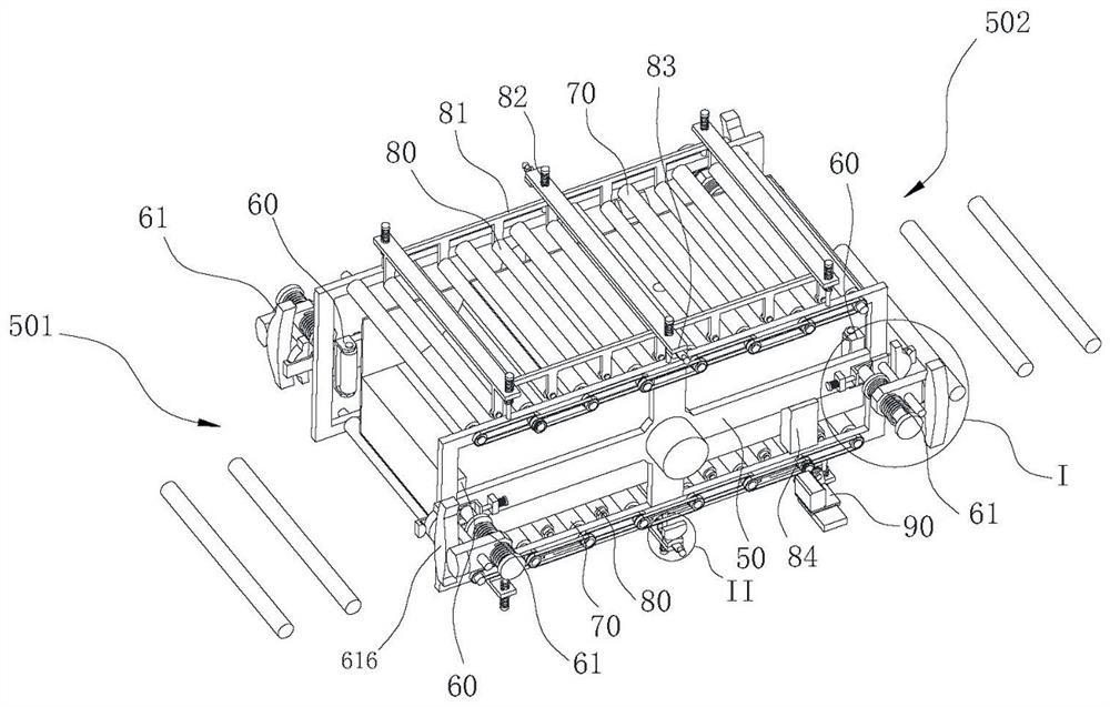
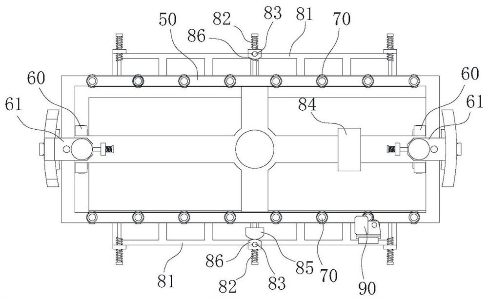
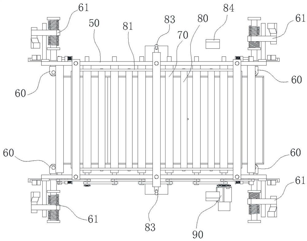
[0028] Such as figure 1 , 2, shown in 3, a kind of overturn channel that is used for electric appliance manufacturing comprises overturn frame 50, and overturn frame 50 is arranged on the frame along the horizontal axis rotation, and overturn frame 50 is provided with the channel that passes through for material, and the length direction of channel and The turning axis of the turning frame 50 is vertical, and the both sides of the turning channel parallel to the axis of the turning frame 50 are provided with conveying rollers 70, and the conveying rollers 70 are arranged at intervals along the length direction of the turning channel, and the turning frame 50 is also provided with floating rollers 80. The floating rollers 80 are arranged in two rows and correspond to the conveying rollers 70 on both sides respectively. The floating rollers 80 are movably arranged on the overturn frame 50 and the floating rollers 80 are assembled to move between the following two stations: stati...

Embodiment 2

[0039] A method for cleaning the surface of a foaming box applying the inversion channel described in Example 1, comprising the steps of:

[0040] Step 1: Transfer the foamed box to the first cleaning station, with the back of the box facing up. At the first cleaning station, use a hand-held dry ice cleaning gun to clean the foaming agent overflowing from the back and sides of the box. cleaning;

[0041] Step 2: Send the box into the turning channel, and the turning channel turns the box over to face up, and then transports the box to the second cleaning station;

[0042] Step 3: At the second cleaning station, clean the front of the box and the surface of the inner tank with a hand-held dry ice cleaning gun;

[0043] In the step 2, the flipping method is:

[0044] Turn the overturning channel to a horizontal posture, adjust the material retainer 60 at the feeding end to station two, and adjust the material retainer 60 at the discharge end to station one;

[0045]The box is...


PUM


Abstract

The invention belongs to the technical field of electric appliance production and manufacturing, and particularly relates to a turnover channel for electric appliance manufacturing, which comprises aturnover frame. The turnover frame is rotatably arranged on a rack along a horizontal axis; a channel for materials to pass through is arranged on the turnover frame; the length direction of the channel is perpendicular to the turnover axis of the turnover frame; conveying rollers are arranged on the two sides, parallel to the axis of the turnover frame, of the turnover channel; the multiple conveying rollers are arranged in the length direction of the turnover channel at intervals; floating rollers are further arranged on the turnover frame; material blocking mechanisms are arranged at the two ends of the channel; and each material blocking mechanism comprises material blocking frames arranged at the two ends of the turnover frame. The floating rollers are arranged on the upper side and the lower side of the turnover channel, so that materials are effectively prevented from shaking and impacting in the subsequent turnover process of the turnover channel, and the materials are prevented from being damaged; and two materials can be turned over and turned around when the turnover channel turns over for one circle, so that the production efficiency is doubled.

Description

technical field [0001] The invention belongs to the technical field of electric appliance manufacturing, and in particular relates to a reversing channel for electric appliance manufacturing. Background technique [0002] Electrical cabinets such as refrigerators and freezers generally adopt a foaming process to form an insulation layer between the outer shell and the inner tank. During the process, the box needs to be turned over. The existing turning equipment is prone to impact during the turning process, which will cause damage to the surface of the box. In addition, the existing turning equipment has an unreasonable structural design and a long mechanism stroke , the action efficiency is low. Contents of the invention [0003] The object of the present invention is to provide a reversing channel for electrical appliances, which can prevent bumps and improve processing efficiency. [0004] The technical scheme that the present invention takes is specifically as follo...

Claims


Application Information

Patent Timeline
Patent Type & Authority Applications(China)
IPC IPC(8): B65G47/88B65G47/248B65G13/00
CPCB65G47/8823B65G47/248B65G13/00
Inventor 廖玉琴
Owner 安徽智汇和科技服务有限公司
Why Eureka
Try Eureka