Auger rack with vertical securement means for suspended storage, use and/or transport of augers or drill bits

a technology of vertical securement and auger rack, which is applied in the field of construction or farm implements, can solve the problems of cumbersome transportation of augers from one location, difficulty in safely transporting a plurality of augers simultaneously, and inability to effectively store or secure augers. to achieve the effect of preventing sway

Inactive Publication Date: 2015-07-30
HOKANSON CRAIG RICHARD
View PDF37 Cites 39 Cited by
  • Summary
  • Abstract
  • Description
  • Claims
  • Application Information

AI Technical Summary

Benefits of technology

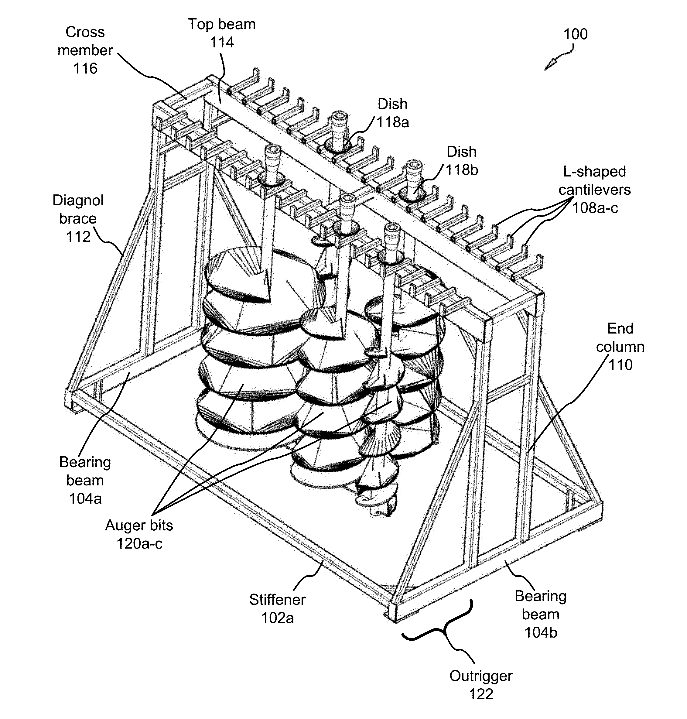
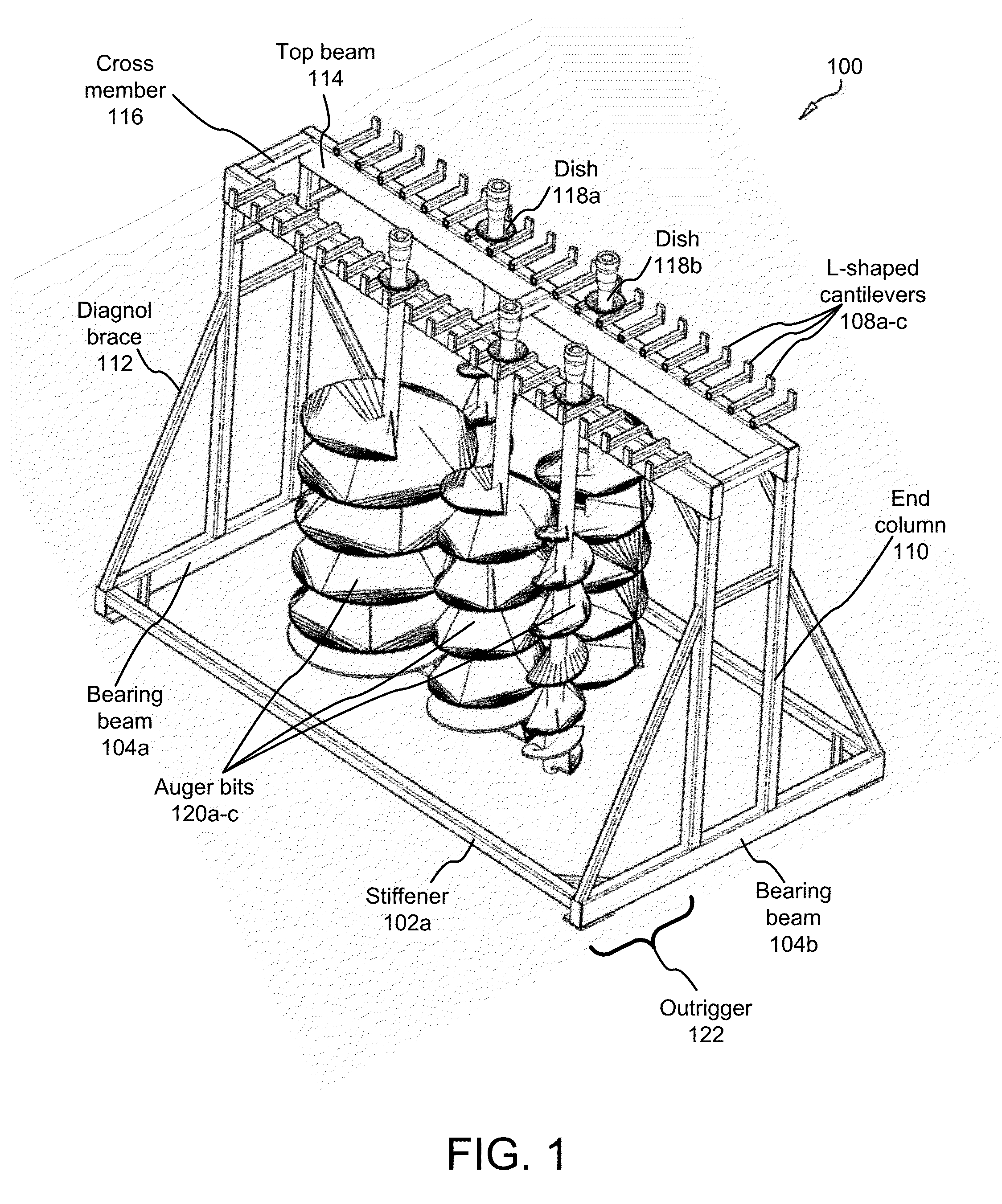
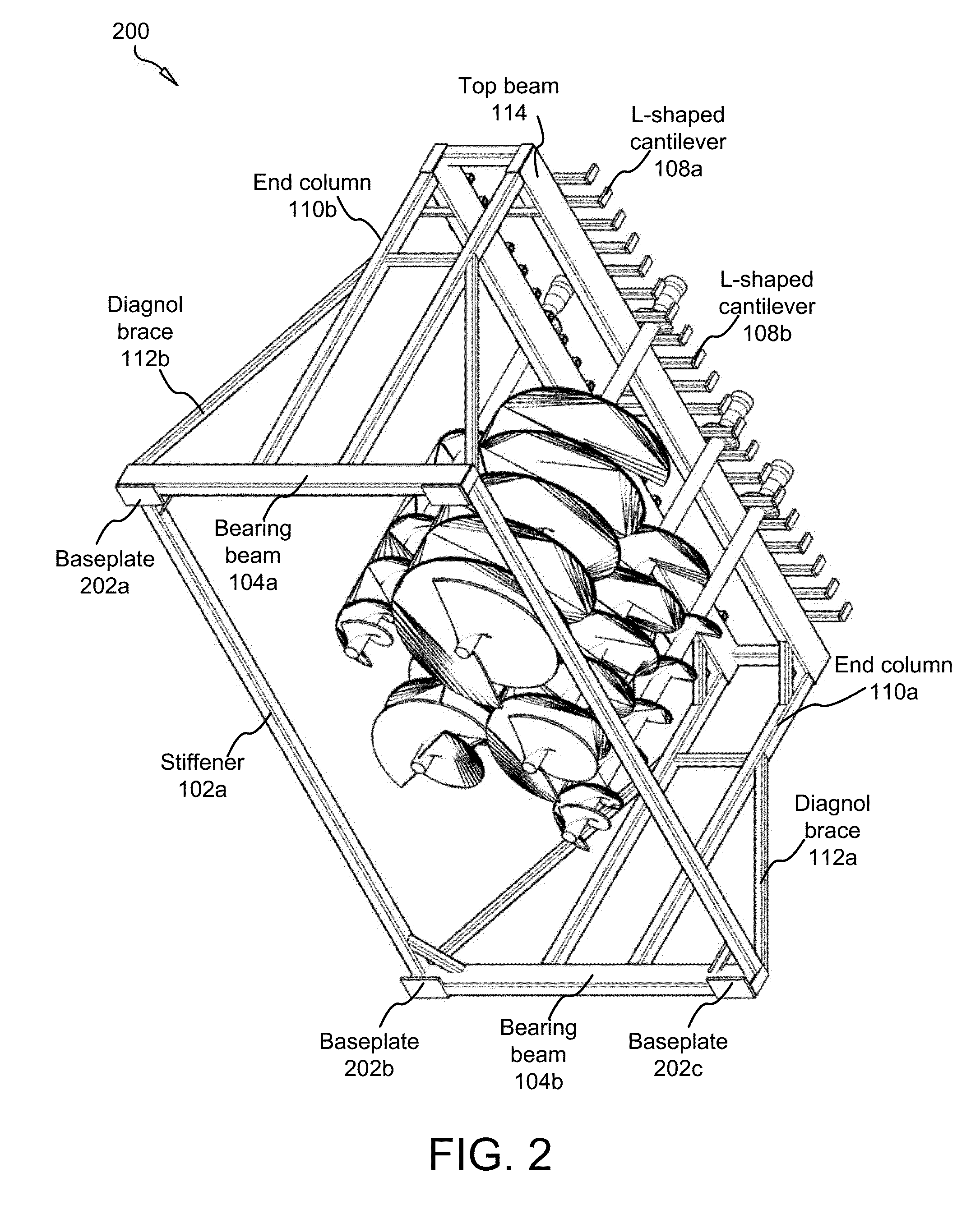
[0016]The method may further comprise transporting augers in a ready to use position in a rack integrated into the design of one of a trailer and truck bed, the augers suspending from one of brackets and L-shaped cantilevers. In some embodiments, the method comprises securing the augers on the rack to prevent swaying.
[0017]Another auger rack for suspending augers is also disclosed, the auger rack comprising: a generally rectangular frame comprising: one or more bearing beams between 0.1 meters and 20 meters in length, the beaming beams comprising elongated components formed from a rigid metallic substance, each bearing beam affixed to one or more upwardly rising end columns; two or more upwardly rising end columns, between 0.2 meters and 7 meters in length, the end columns comprising elongated components formed from a rigid metallic substance, each end column affixed to a bearing beam and to a top beam; or more top beams between 0.2 meters and 10 meters in length, the top beams comprising elongated structural components formed from a rigid metallic substance, each top beam affixed to one or more end columns; a plurality of brackets affixed in parallel to a top beam for suspending auger bits, wherein auger bits are suspended between the brackets.
[0018]One or more of the end columns and the bearing beams may comprise I-beams. The brackets may be evenly spaced apart from one another. The auger rack may be affixed to one of a truck bed and trailer.
[0019]These features and advantages of the present invention will become more fully apparent from the following description and appended claims, or may be learned by the practice of the invention as set forth hereinafter.

Problems solved by technology

The augers themselves are cumbersome to transport from one location to another as well as to store.
Because of their size, it is difficult to safely transport a plurality of augers simultaneously, and there exists no efficient means in the art of storing or securing augers during transport, much less means of doing so by a single human operator.
This approach is prone with difficulty and danger to the operator.
It can be very dangerous for a single operator, or even two operators, to attempt to ready the auger, vehicle, and auger drive unit alone.

Method used


Image

  • Auger rack with vertical securement means for suspended storage, use and/or transport of augers or drill bits
  • Auger rack with vertical securement means for suspended storage, use and/or transport of augers or drill bits
  • Auger rack with vertical securement means for suspended storage, use and/or transport of augers or drill bits

Examples


Embodiment Construction

[0031]Reference throughout this specification to “one embodiment,”“an embodiment,” or similar language means that a particular feature, structure, or characteristic described in connection with the embodiment is included in at least one embodiment of the present invention. Thus, appearances of the phrases “in one embodiment,”“in an embodiment,” and similar language throughout this specification may, but do not necessarily, all refer to the same embodiment.

[0032]Furthermore, the described features, structures, or characteristics of the invention may be combined in any suitable manner in one or more embodiments. In the following description, numerous specific details are provided to provide a thorough understanding of embodiments of the invention. One skilled in the relevant art will recognize, however, that the invention may be practiced without one or more of the specific details, or with other methods, components, materials, and so forth. In other instances, well-known structures, ...


PUM


Abstract

A rack is disclosed, adapted to facilitate efficient transport and interchange of augers and/or mining drill bits used in construction by either single operator or a plurality of operators. The rack comprises a plurality of elongated members affixed to one another; and, in some embodiments, a plurality of L-shaped, cantilevered brackets from which augers or drill bits are suspended during transport, storage, interchange, and the like.

Description

CROSS-REFERENCE TO OTHER APPLICATIONS[0001]This patent application claims priority to, and incorporates, U.S. provisional patent application Ser. No. 14 / 795,476 entitled “Auger Rack with Vertical Securement Means for Suspended Storage, Use and / or Transport of Augers or Drill Bits” filed on Jan. 25, 2013 for Craig Richard Hokanson.BACKGROUND OF THE INVENTION[0002]1. Field of the Invention[0003]This invention relates to construction or farm implements, and more particularly relates to an implement for storage or transportation and interchange of augers used in drilling earth in connection with construction.[0004]2. Description of the Related Art[0005]Augers and drilling apparati are well-known in the art. Earth augers comprise sharp helical tools, varying in width from only a few centimeters to several meters, used in drilling to extract earth and aggregate from a ground surface in a construction area. Augers are also used to facilitate the construction of wells, footings, mines, unde...

Claims


Application Information

Patent Timeline
Patent Type & Authority Applications(United States)
IPC IPC(8): B25H3/00B62D33/00E21B7/02E21B7/00B25H3/04A47B81/00
CPCB25H3/003B25H3/04B62D33/00E21B7/027E21B7/005A47B81/00E21B10/44E21B19/14
Inventor HOKANSON, CRAIG RICHARD
Owner HOKANSON CRAIG RICHARD
Why Eureka
Try Eureka