Pipe hanger

a technology of pipe hangers and pipes, which is applied in the direction of machine supports, other domestic objects, mechanical equipment, etc., can solve the problems of difficult installation of pipes, complicated installation of pipes, and inability to easily install pipes

Inactive Publication Date: 2009-06-16
B&I
View PDF18 Cites 39 Cited by
  • Summary
  • Abstract
  • Description
  • Claims
  • Application Information

AI Technical Summary

Benefits of technology

[0018]Yet another object of the present invention is to provide a pipe hanger, capable of preventing swaying caused by external impacts and unfastening of a supporting rod fixed to a ceiling by providing a resiliently biasing means in a supporting bracket to retain a nut block, readily installing a pipe while readily locking and unlocking a locking plate or rod, which is coupled into the mounting plates of a one-side semicircular band and the supporting bracket, to and from a locking assembly mounted to the mounting plate of the other-side semicircular band, and supporting the pipe seated by a hook of the one-side semicircular band which is formed to extend beyond a vertical center line to thereby prevent the seated pipe from falling down as well as to readily mount the other-side semicircular band.
[0020]a pad (14) coupled to inner surfaces of the semicircular bands (2 and 3), and contacting the supported pipe to damp vibration from the pipe;

Problems solved by technology

For this reason, the installation is very complicated.
Hence, the pipe cannot be readily installed.
As such, the installation of the pipe is very complicated, and the pipe should be installed while being supported, so that it cannot be readily installed.
Further, because it takes much time to install the pipe, working efficiency is lowered.
Because the retaining piece 54 and the annular coil spring 58 are discrete components, at least one of them may be lost, which would make it impossible to install the pipe.
Hence, the pipe hanger vibrates and is rotated by external impacts, so that the supporting rod is gradually unfastened from the nut block, thereby being reduced in its ability to fully support the pipe.
Hence, when being subjected to vibration due to external impacts or earthquakes, the pipe hanger does not dampen (prevent) the vibration.
Furthermore, when such vibration is strong, the pipe is twisted or separated from the pipe hanger.

Method used


Image

  • Pipe hanger
  • Pipe hanger
  • Pipe hanger

Examples


Embodiment Construction

[0031]Reference will now be made in greater detail to a preferred embodiment of the invention, an example of which is illustrated in the accompanying drawings. Wherever possible, the same reference numerals will be used throughout the drawings and the description to refer to the same or like parts.

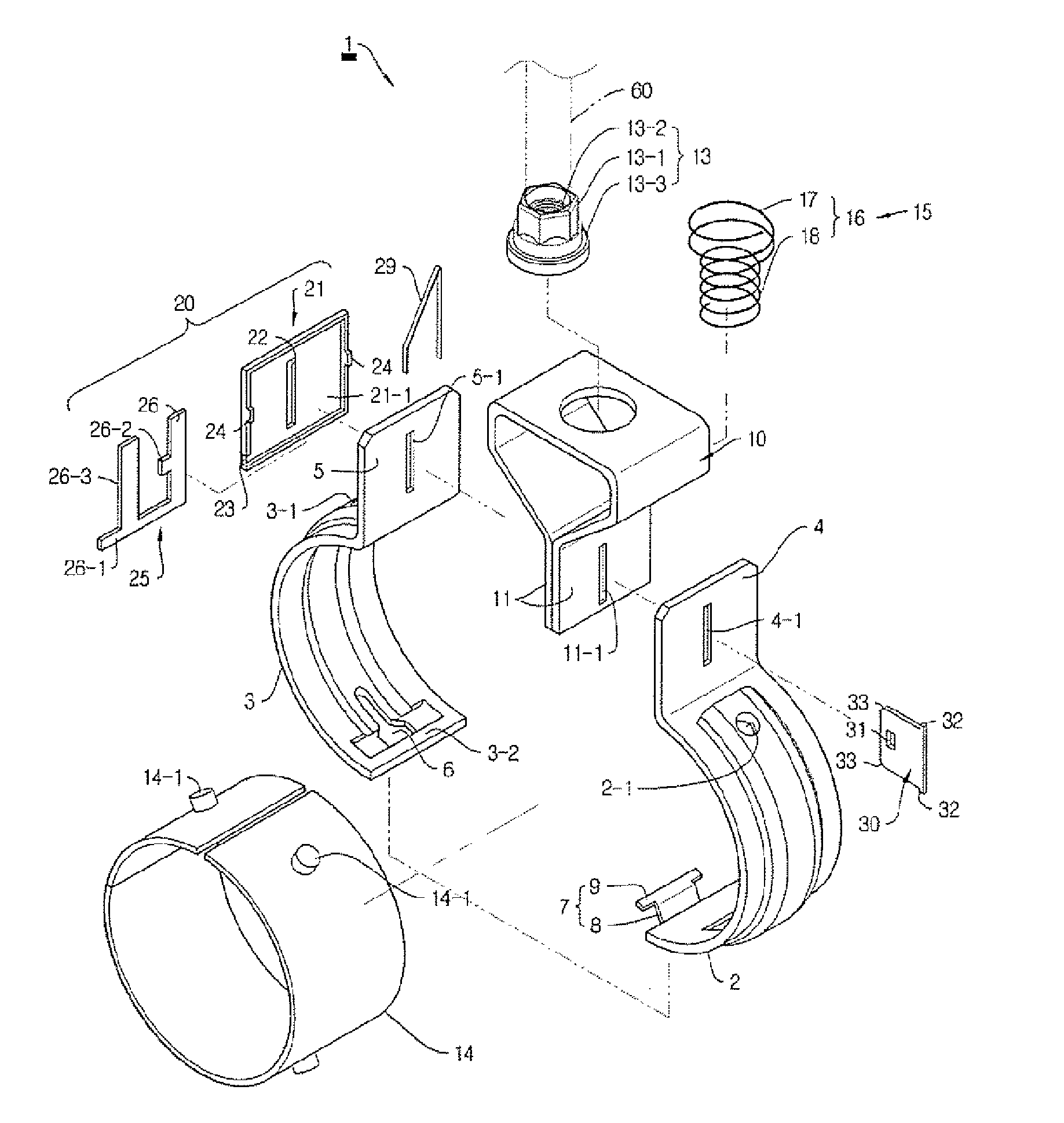
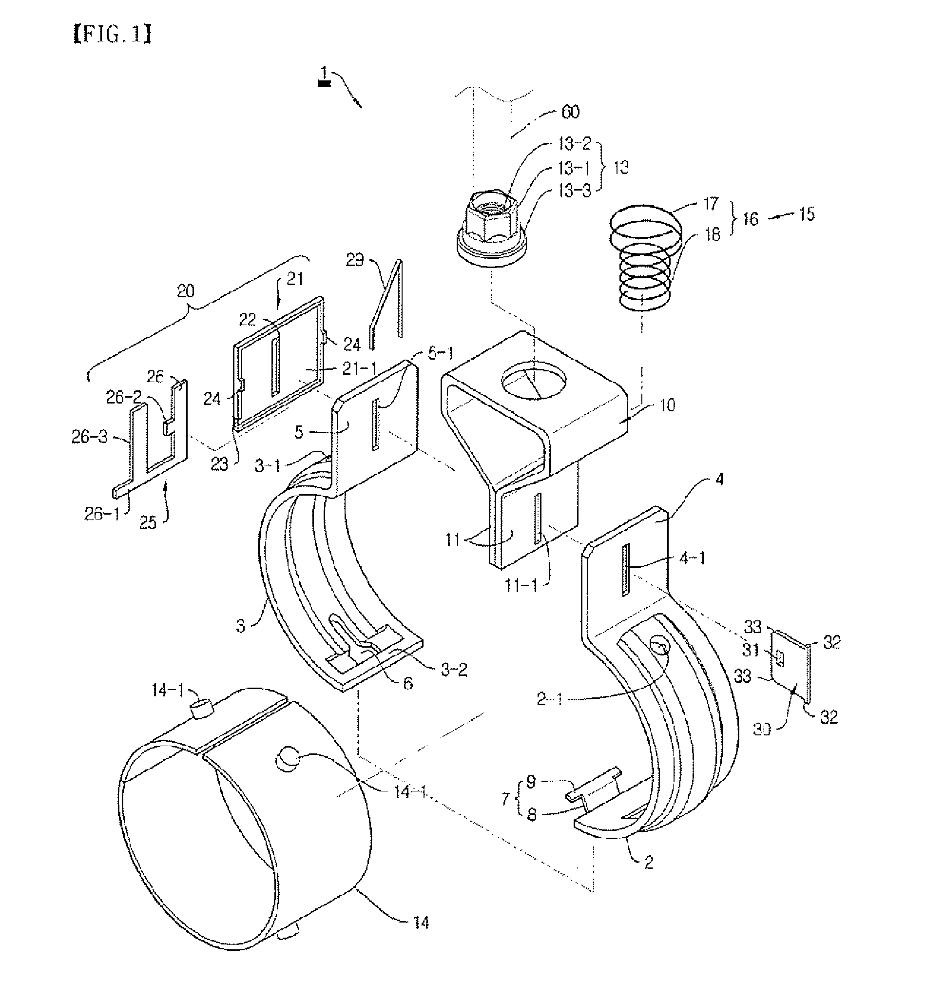
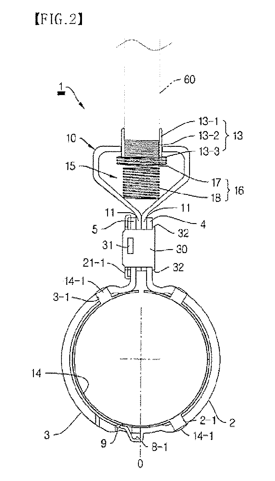
[0032]FIGS. 1, 2, 3A, 3B, 4A to 4C, and 5A to 5C illustrate embodiments of a pipe hanger 1 according to the present invention. More Specifically, FIGS. 1, 2, and 3A ant 3B are an exploded perspective view, an assembled sectional view, and views for explaining operation, of a pipe hanger 1 according to the present invention. FIGS. 4A and 5A and, 4B and 4C and 5B and 5C are exploded perspective views, and views for explaining operation, of different pipe hangers 1-1 and 1-2 according to the present invention.

[0033]Referring to FIGS. 1, 2, 3A and 3B, the pipe hanger 1 according to the present invention is constructed as follows.

[0034]A pair of semicircular bands 2 and 3 is formed so as to be ...


PUM


Abstract

A pipe hanger hooks or unhooks lower ends of semicircular bands divided left and right by means of a hooking means, mounts mounting plates integrally formed at the lower end of a supporting bracket to mounting plates integrally formed at upper ends of the semicircular bands, provides a resiliently biasing means in the supporting bracket to resiliently bias a nut block in an upward direction, couples a locking plate or rod into the mounting plates of the other-side semicircular band and the supporting bracket, mounts a locking cap and a locking guide to the mounting plate of the one-side semicircular band, and forms a hook of the lower end of the other-side semicircular band so as to extend beyond the vertical center line of an inner space defined by the semicircular bands. Thereby, the resiliently biasing means is provided in the supporting bracket to thus retain block.

Description

BACKGROUND OF THE INVENTION[0001]1. Field of the Invention[0002]The present invention relates, in general, to a pipe hanger used to install a pipe to the ceiling or wall of a building. More particularly, the present invention is directed to provide a pipe hanger, in which lower ends of semicircular bands divided left and right are hooked and unhooked by a hooking means, and mounting plates integrally formed at the lower end of a supporting bracket are mounted to the mounting plates integrally formed at upper ends of the semicircular bands, thereby obtaining a damping effect on vibration or external impacts by providing a resiliently biasing means to the supporting bracket, readily locking or unlocking a locking plate, inserted into the mounting plate of each semicircular band and the mounting plates of the supporting bracket, to or from a locking assembly, and easily supporting the installed pipe by forming a hook of the lower end of the other-side semicircular band to expend beyond...

Claims


Application Information

Patent Timeline
Patent Type & Authority Patents(United States)
IPC IPC(8): F16L3/00
CPCF16L3/1008F16L3/11F16L3/00F16L3/10
Inventor KIM, TAE SIK
Owner B&I
Why Eureka
Try Eureka