Shore-type wave energy generating device

A power generation equipment and wave energy technology, which is applied in the field of wave energy power generation equipment, can solve the problems of small power generation, dumping, and increased maintenance costs, and achieve the effects of increasing longitudinal wave energy, avoiding violent shaking, and improving power generation efficiency

Inactive Publication Date: 2018-11-30
WENZHOU CHONGYA ELECTRONICS TECH
View PDF6 Cites 2 Cited by
  • Summary
  • Abstract
  • Description
  • Claims
  • Application Information

AI Technical Summary

Problems solved by technology

[0002] Wave energy is a specific form of ocean energy, and it is also one of the most important energy sources in ocean energy. Its development and utilization are very important to alleviate the energy crisis and reduce environmental pollution. The turbulent wave movement produces huge and eternal And environmental protection energy, if the kinetic energy of ocean waves and other water surface wave energy can be fully utilized, the prospect of world energy will be quite broad and bright. Although wave energy in the ocean is difficult to extract, coastal areas with better conditions The wave energy still has abundant resource reserves. At present, the utilization of shore-type wave energy is mainly used for power generation. The efficiency is low, and the power generation is small, which cannot meet the balance of income and expenditure, and the practicability is poor. In addition, most of the power generation equipment is not firmly installed, the stability is poor, and it is very easy to dump under the action of sea wind, which will cause a decrease in maintenance costs in the later period. Increase

Method used


Image

  • Shore-type wave energy generating device
  • Shore-type wave energy generating device
  • Shore-type wave energy generating device

Examples


Embodiment Construction

[0023] The following will clearly and completely describe the technical solutions in the embodiments of the present invention with reference to the accompanying drawings in the embodiments of the present invention. Obviously, the described embodiments are only some, not all, embodiments of the present invention. Based on the embodiments of the present invention, all other embodiments obtained by persons of ordinary skill in the art without making creative efforts belong to the protection scope of the present invention.

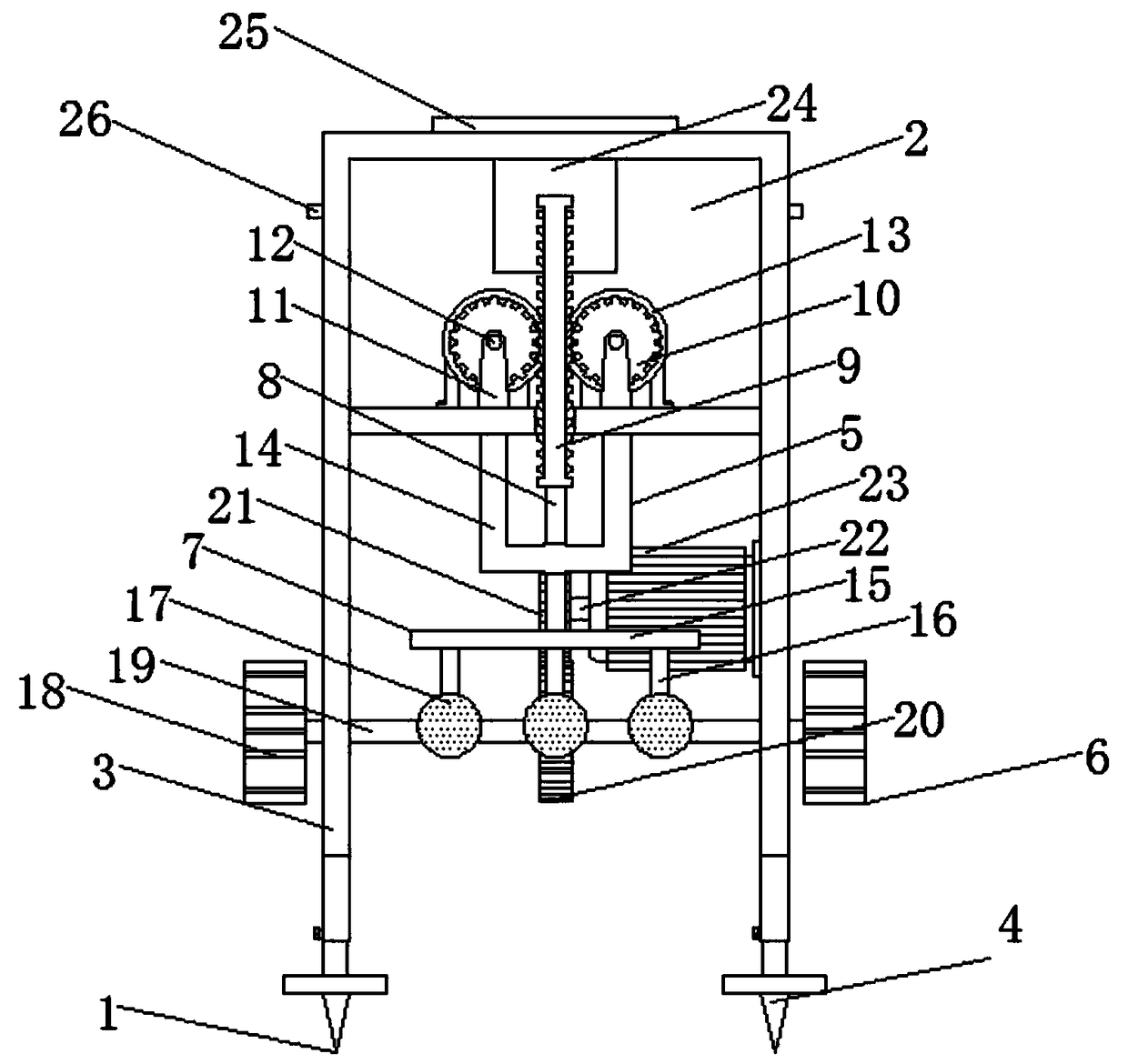
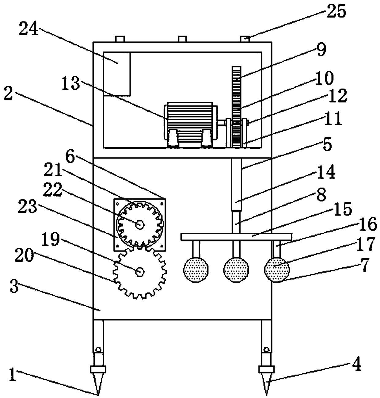
[0024] see Figure 1-5, the present invention provides a technical solution: a shore-type wave energy power generation equipment, including a device body 1, a top box 2, a support plate 3, a support leg 4, a vertical wave generator 5, a shear wave generator 6, a floater 7, Ejector 8, rack 9, gear 10, support 11, rotating shaft 12, first generator 13, guide frame 14, fixed plate 15, connecting rod 16, floating ball 17, impeller 18, connecting shaft 19, driving ...


PUM


Abstract

The invention discloses a shore-type wave energy generating device. The top of a device body is provided with a top box, the front side in the top box is equipped with a vertical wave generator, and the bottom end of the vertical wave generator is equipped with a floating device. The top of the floating device is fixedly connected with an ejection rod, the top of the ejection rod is fixedly connected with a rack, two sides of the rack are meshed with gears, and the middles of the gears are provided with a rotating shaft. One end of the rotating shaft is equipped with a first generator, and twosides of the bottom of the top box are provided with support plates. A transverse wave generator is mounted on the rear sides of the support plates, a connecting shaft is arranged in the middle of the transverse wave generator, a driving gear is mounted in the middle of the connecting shaft, and a driven gear is meshed on the top of the driving gear. A transmission shaft is installed in the middle of the driven gear, and a second generator is installed at one end of the transmission shaft, and support legs are installed on two sides of the bottoms of the support plates. The support plates andthe support legs are fixedly connected by screws, the operation is simple, installation, removal, repair and replacement of the support legs are facilitated, and the applicable range of the device body is expanded.

Description

technical field [0001] The invention relates to the technical field of wave energy generating equipment, in particular to shore-type wave energy generating equipment. Background technique [0002] Wave energy is a specific form of ocean energy, and it is also one of the most important energy sources in ocean energy. Its development and utilization are very important to alleviate the energy crisis and reduce environmental pollution. The turbulent wave movement produces huge and eternal And environmental protection energy, if the kinetic energy of ocean waves and other water surface wave energy can be fully utilized, the prospect of world energy will be quite broad and bright. Although wave energy in the ocean is difficult to extract, coastal areas with better conditions The wave energy still has abundant resource reserves. At present, the utilization of shore-type wave energy is mainly used for power generation. The efficiency is low, and the power generation is small, which...

Claims


Application Information

Patent Timeline
Patent Type & Authority Applications(China)
IPC IPC(8): F03B13/18F03B13/22F21V23/04F21Y115/10
CPCF03B13/1815F03B13/22F21V23/0464F21Y2115/10Y02E10/30
Inventor 谢高彬
Owner WENZHOU CHONGYA ELECTRONICS TECH
Why Eureka
Try Eureka