
A rotating 360-degree product burr detection device
A detection device and a rotating technology, which is applied in the direction of optical testing for flaws/defects, etc., can solve the problems of high detection error rate, easy damage, low assembly pass rate, etc., and achieve the effect of stable transportation
- Summary
- Abstract
- Description
- Claims
- Application Information
AI Technical Summary
Problems solved by technology
Method used
Image

Examples
Embodiment Construction
[0042] The present invention will be described in further detail below in conjunction with the accompanying drawings. It should be noted that the words "front", "rear", "left", "right", "upper" and "lower" used in the following description refer to the directions in the drawings, and the words "inner" and "outer ” refer to directions towards or away from the geometric center of a particular part, respectively.
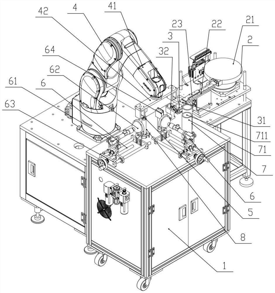
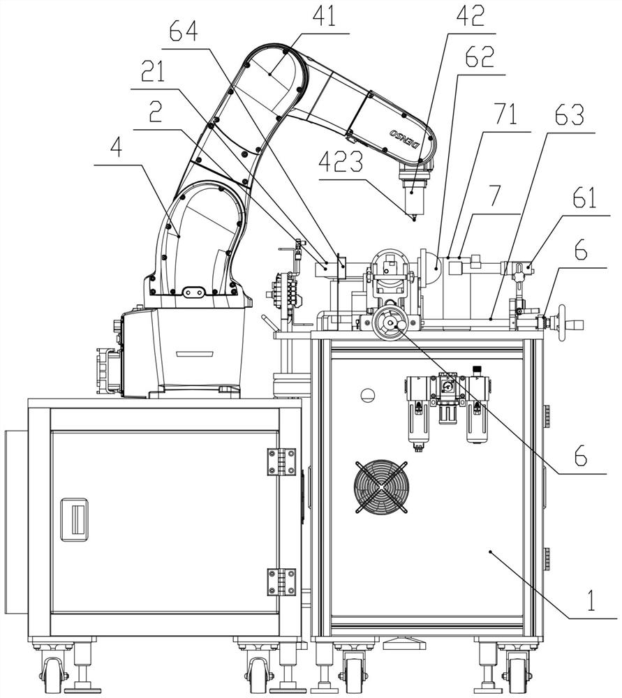
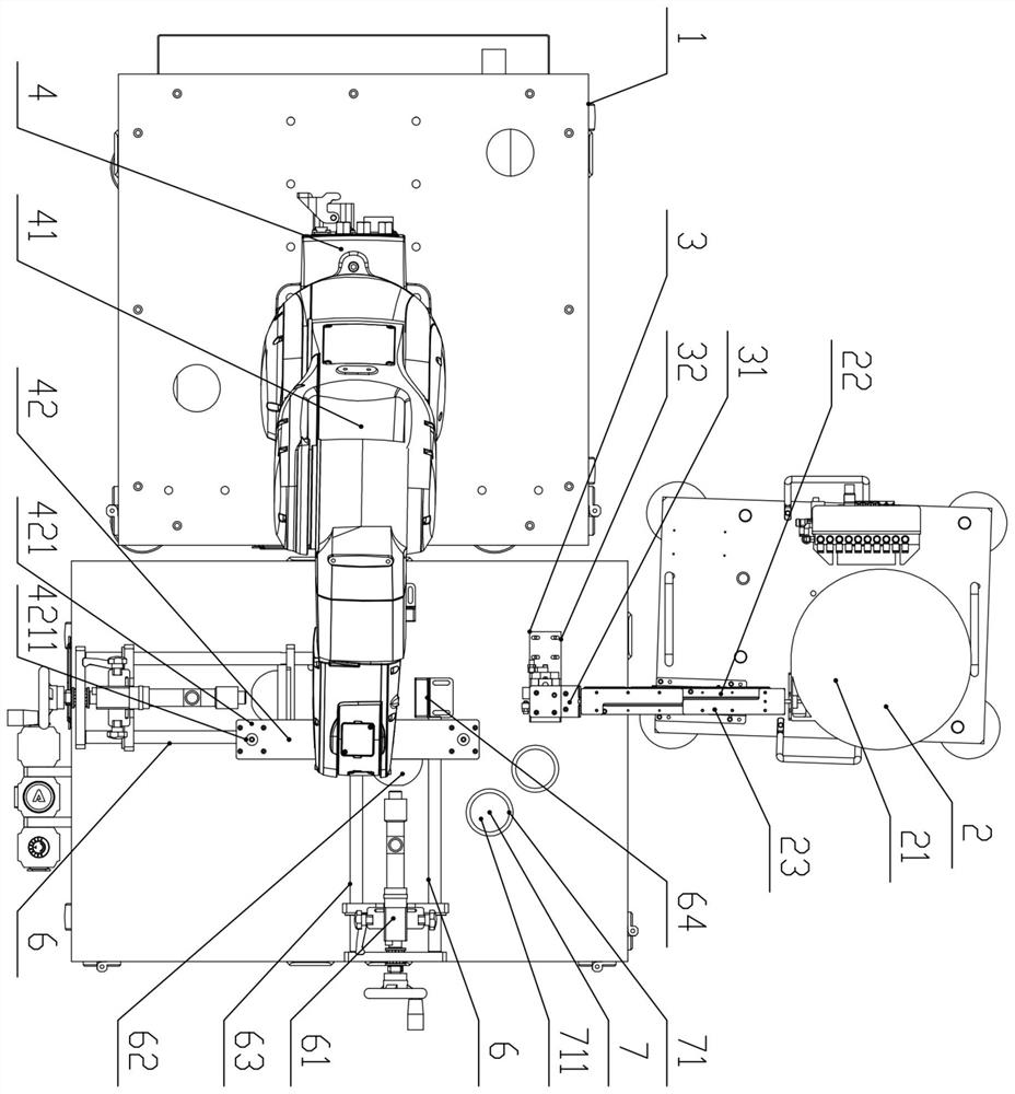
[0043] Figure 1 to Figure 10 A rotating 360-degree product burr detection device according to an embodiment of the present invention is schematically shown. As shown in the figure, the device includes a workbench 1, a material loading part 2, a material distribution part 3, a material transfer part 4, a rotating jig 5, a detection part 6 and a placement part 7,
[0044] Workbench 1 is set on the ground,
[0045] The feeding part 2 includes a vibrating plate 21 and a vibrating guide rail 22 fixed on the right side of the workbench 1, and the discharge port on the le...
PUM
 Abstract
Description
Claims
Application Information