Adaptive stepless tie piece plate with adjustable pedal angle

A pedal angle and self-adaptive technology, applied in the field of lacing boards, can solve the problems of inability to tighten the calf, affect the effect of lacing, and can not be done, so as to simplify the process of adjusting the inclination of the pedals, reduce the adjustment complexity, Avoid the effects of bad actions

Inactive Publication Date: 2018-12-18
淄博正邦知识产权企划有限公司
View PDF7 Cites 6 Cited by
  • Summary
  • Abstract
  • Description
  • Claims
  • Application Information

AI Technical Summary

Problems solved by technology

[0003] Existing lacing boards usually include pedals, bottom boards and foot guards. A support board is provided at the bottom of the pedals to adjust the inclination angle of the pedals. However, no matter what the adjustment structure is, the user needs to leave the pedals and bend down to adjust manually.
While stretching, the leg muscles are in a tense state, leaving the pedal to adjust the angle will make the muscles relax, and then stand on the pedal again to stretch, this up and down will make the leg muscles tight and loose, and it is impossible to do it step by step Stretching, which seriously affects the effect of stretching and user experience
[0004] In addition, the standard stretching posture is to keep the legs upright on the pedals. Only at this time can the leg muscles be well stretched and the stretching effect can be achieved. Unbearable to tense calves
In the prior art, the adjustment of the pedal angle is divided into gears, such as third gear, fourth gear, fifth gear, etc., which need to be adjusted manually, but because the gears are fixed, for some people, it is impossible to find a suitable gear. Either the calves cannot get enough stretching strength, or the stretching degree is too large, causing discomfort in the legs, which seriously affects the effect of stretching

Method used


Image

  • Adaptive stepless tie piece plate with adjustable pedal angle
  • Adaptive stepless tie piece plate with adjustable pedal angle
  • Adaptive stepless tie piece plate with adjustable pedal angle

Examples


Embodiment 1

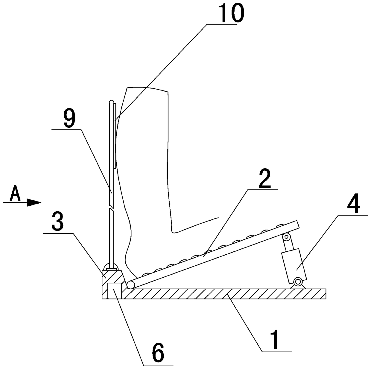
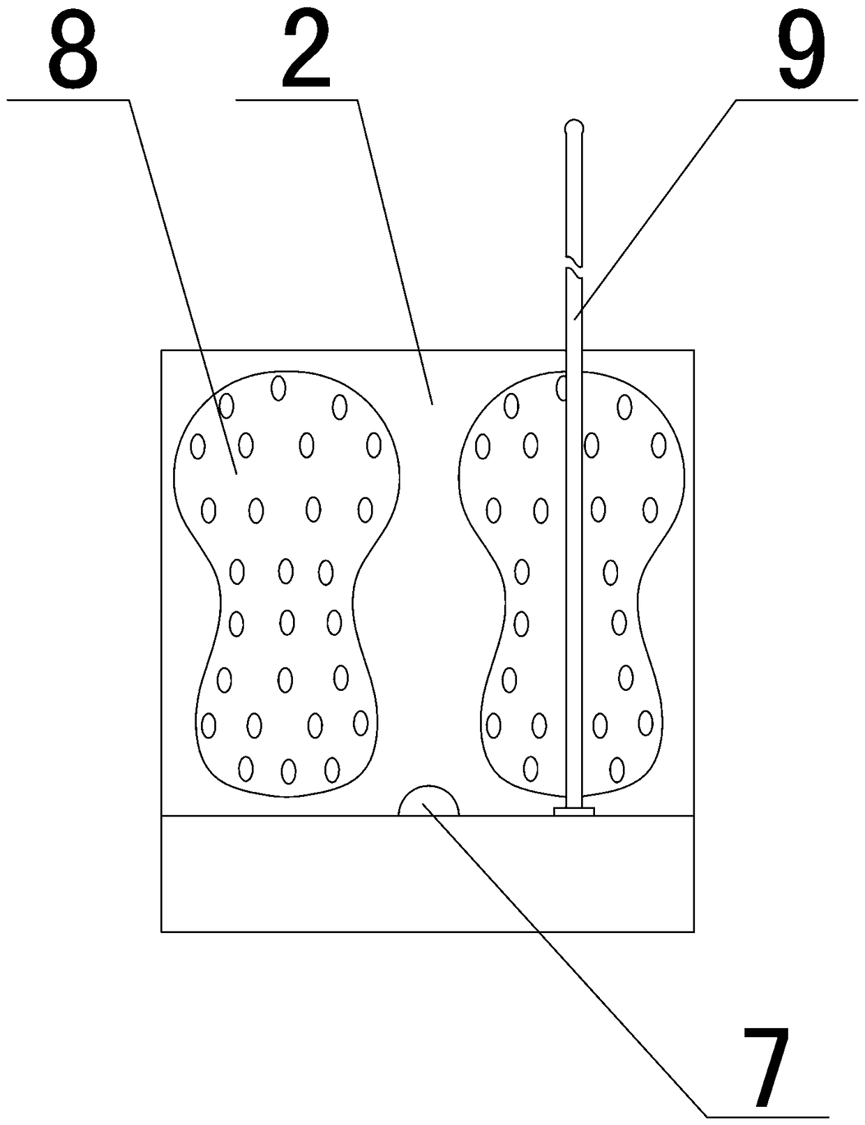
[0029] Such as Figure 1~Figure 3 As shown, a self-adaptive and stepless adjustable pedal angle lacing plate includes a bottom plate 1, a pedal 2. The lower end of the pedal 2 is hinged with the bottom plate 1, and the bottom plate 1 near the hinged end of the pedal 2 is provided with a foot stop 3 and a foot stop 3 A vertical detection rod 9 is fixed on the rear side, and a contact sensor is fixed to the front of the detection rod 9.

[0030] It also includes a controller 6, a pedal adjustment mechanism and a switch 7. The controller 6 is arranged at the bottom of the foot guard 3, and the pedal adjustment mechanism is arranged below the pedal 2. In this embodiment, the pedal adjustment mechanism is a push rod motor 4. The push rod motor 4 is hinged with the bottom plate 1. The top of the push rod of the push rod motor 4 is hinged with the upper part of the pedal 2, and the push rod extension of the push rod motor 4 can drive the pedal 2 to be hinged around Point rotation. A sw...

Embodiment 2

[0037] Such as Figure 4~Figure 6 As shown, an electric ribbed plate includes a bottom plate 1 and a pedal 2, and a foot stop 3 is provided at the lower end of the pedal 2. The left and right sides of the bottom plate 1 are respectively provided with a boss 11, the inner side of the boss 11 is provided with a front-to-rear long slideway 12, and a horizontal slide bar 13 is provided in the slideway 12 on both sides. The slide bar 13 can It slides back and forth in the slideway 12, and a front-to-rear propulsion rod 14 is fixed in the middle of the sliding rod 13, and the propulsion rod 14 is an internal threaded cylindrical structure. A rotating electric machine 16 is fixed on the base 1 below the pedal 2, and a screw 15 is fixed at the shaft end of the rotating electric machine 16. The shaft of the rotating electric machine 16 and the screw 15 are fixedly connected by a sleeve 17 to enable the two The connection is more stable. The external thread of the screw 15 matches the ...

specific Embodiment approach

[0040] First, turn on the power of the rotating motor 16 and the user stands on the pedal 2 with his heel close to the foot stopper 3, and the foot stopper 3 can prevent both feet from leaving the pedal 2. If the user needs to adjust the inclination angle of the pedal 2 to meet different degrees of leg stretching, just use the up button or down button of the foot switch 7 to drive the shaft of the rotating motor 16 to rotate forward or backward, thereby driving the lead screw 15 to rotate , The push rod 14 forwards or retreats, drives the sliding rod 13 to advance or retreat along the slideway 12, so that the bottom of the pedal 2 advances or retreats in the horizontal direction, the pedal 2 as a whole rotates around the hinge point of the support rod 18, thereby adjusting the tilt of the pedal 2 The effect of perspective. During the whole process, the user only needs to step on the switch 7 on the pedal 2 without leaving the pedal 2, which is convenient for the user to adjust ...


PUM


Abstract

The invention provides an adaptive stepless tie piece plate with an adjustable pedal angle, and belongs to the field of sports equipment. The adaptive stepless tie piece plate comprises a bottom plate, a pedal and a foot baffle, wherein the end of the pedal is hinged to the bottom plate, the foot baffle is arranged at the rear side of the lower end of the pedal, the adaptive stepless tie piece plate is characterized in that the rear side of the foot baffle is fixedly provided with a vertical gauge rod, and the front side of the gauge rod fixes a contact sensor; the adaptive stepless tie pieceplate further comprises a controller and a pedal adjusting mechanism, wherein the pedal adjusting mechanism and the contact sensor are electrically connected with the controller respectively. According to the adaptive stepless tie piece plate with the adjustable pedal angle, double feet of a user can adjust the inclined angle of the pedal without leaving the pedal when the tie piece plate is in use, and the gradient of the pedal can be automatically adjusted according to the physical condition of the user.

Description

Technical field [0001] The invention belongs to the field of sports fitness equipment, and in particular relates to a self-adaptive and stepless adjustable pedal angle. Background technique [0002] Stretching board, as the name suggests, is a kind of exercise equipment for stretching muscles and collaterals. It mainly uses the inclination angle of the pedal to stretch the leg muscles, so that the muscles on the back of the legs can be effectively exercised, which can relax the muscles and promote blood circulation, and promote the legs. The blood circulation in the body and even the whole body is smoother, which is in line with the physiotherapy concept of Chinese medicine. At the same time, when the user is standing on the stretcher, the body is upright, especially the shoulders, neck, buttocks and other parts are balanced and upright, which promotes uniform muscle force throughout the body, which is beneficial to improve the body shape, and frequent use can help the user to ha...

Claims


Application Information

Patent Timeline
Patent Type & Authority Applications(China)
IPC IPC(8): A63B22/04A63B23/04A63B24/00
CPCA63B22/04A63B23/04A63B24/0087
Inventor 任祥生
Owner 淄博正邦知识产权企划有限公司
Why Eureka
Try Eureka