Rear-mounted beam-splitting pupil laser differential confocal Raman spectroscopy test method and device

A spectral testing and differential confocal technology, applied in measuring devices, Raman scattering, analyzing materials, etc., can solve the problems of low spatial resolution and large limitations, simplify the optical path structure, and improve the signal-to-noise ratio of spectral signals , Improve the effect of system horizontal resolution

Inactive Publication Date: 2019-01-15
BEIJING INSTITUTE OF TECHNOLOGYGY
View PDF7 Cites 4 Cited by
  • Summary
  • Abstract
  • Description
  • Claims
  • Application Information

AI Technical Summary

Problems solved by technology

[0008] The purpose of the present invention is to solve the problem that the existing technology is greatly limited by external factors and the spatial resolution is low, and propose a post-divided pupil laser differential confocal Raman spectrum testing method and device

Method used


Image

  • Rear-mounted beam-splitting pupil laser differential confocal Raman spectroscopy test method and device
  • Rear-mounted beam-splitting pupil laser differential confocal Raman spectroscopy test method and device
  • Rear-mounted beam-splitting pupil laser differential confocal Raman spectroscopy test method and device

Examples


Embodiment

[0055] In this embodiment, the light source system 1 uses a 532nm continuous laser, the dichroic spectroscopic system 6 uses a NotchFilter, and the spectral detection unit 11 uses a Raman spectrometer.

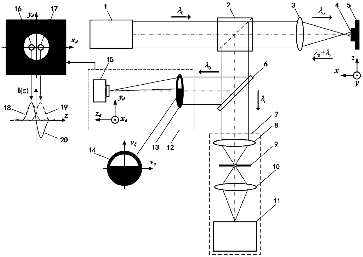
[0056] Such as Figure 11 As shown, the post-splitting pupil laser differential confocal Raman spectroscopy detection process is as follows:

[0057] First, the laser light emitted from the light source system 1 composed of lasers is converged into the second pinhole 25 by the third converging lens 24 , and then collimated and expanded by the fourth converging lens 26 to form a parallel excitation beam. After the excitation beam passes through the radial polarization conversion system 21, the dichroic prism 2 and the pupil filter 22, the measured objective lens 3 converges on the measured sample 4, and excites the Raman scattered light carrying the micro-area characteristic parameters of the measured sample 4 .

[0058] Then the computer 33 controls the three-dimensional sca...


PUM


Abstract

The invention relates to a rear-mounted beam-splitting pupil laser differential confocal Raman spectroscopy test method and device, and belongs to the technical field of microscopic spectral imaging.According to the method, a beam-splitting pupil differential confocal microscopic imaging system is constructed trough Rayleigh scattered light abandoned in a confocal Raman spectroscopy detection system to realize high spatial resolution detection for the geometrical morphology of a sample; and Raman spectroscopy information at a focal point of the sample is precisely acquired by using a focal point information acquired by the beam-splitting pupil differential confocal microscopic imaging system, thus realizing "spectrum-in-one" beam-splitting pupil differential confocal Raman spectroscopy high spatial resolution imaging and detection. The method has the advantages of precise positioning, high spatial resolution, high spectroscopy detection sensitivity and the like and can be widely applied to the field of biomedicines, physical chemistry, precision measurement, femtosecond laser machining and the like.

Description

technical field [0001] The invention relates to a rear split pupil laser differential confocal Raman spectrum testing method and device, and belongs to the technical field of microspectral imaging. The invention combines post-divided-pupil laser differential confocal microscopy technology with Raman spectrum detection technology, and relates to a post-divided-pupil laser differential confocal Raman spectroscopy testing method and device that "integrates images and spectra into one", which can be used for High spatial resolution detection of micro-area Raman spectra of various samples, etc. Background technique [0002] Laser confocal Raman spectroscopy technology changes the frequency shift of the scattered light through the energy exchange between the incident laser and optical phonons, and realizes the non-contact measurement of the composition, concentration, stress, strain, temperature and other parameters of the sample micro-area. Measurement, laser confocal Raman spec...

Claims


Application Information

Patent Timeline
Patent Type & Authority Applications(China)
IPC IPC(8): G01N21/65G01N21/01
Inventor 赵维谦吴寒旭邱丽荣王允
Owner BEIJING INSTITUTE OF TECHNOLOGYGY
Why Eureka
Try Eureka