Conveying and pouring device based on concrete construction of high-rise building

A technology for conveying and pouring and high-rise buildings, applied in the field of concrete pouring, can solve the problems of common quality problems of concrete floors, displacement and deformation of inserted reinforcement, large distribution of protective layer, etc. cracking effect

Pending Publication Date: 2019-03-01
陈兴龙
View PDF0 Cites 3 Cited by
  • Summary
  • Abstract
  • Description
  • Claims
  • Application Information

AI Technical Summary

Problems solved by technology

[0003] 1. In large-area pouring, due to the limitation of the placing machine itself, the distributing radius is small, which cannot meet the actual distributing range. Multiple placing machines are required for cross pouring. In the blind spot of pouring, the material is often cut from the same part of the column or shear wall. Until the concrete is poured, this will often cause excessive side pressure of the single-sided formwork, resulting in mold explosion or expansion; at the same time, because the concrete flows in the same direction, the pressure on both sides is unbalanced, causing the shear wall or column formwork to move in the same direction. Biased
[0004] 2. Before setting up the placing machine, it is necessary to reserve enough working space and the mechanical self-weight load directly acts on the pouring surface, which may easily cause displacement, deformation, damage or blockage of the formwork, steel bars, reserved holes, embedded parts, and inserting bars.
[0005] 3. When pouring concrete at

Method used


Image

  • Conveying and pouring device based on concrete construction of high-rise building
  • Conveying and pouring device based on concrete construction of high-rise building
  • Conveying and pouring device based on concrete construction of high-rise building

Examples


Embodiment Construction

[0052] The technical solutions in the embodiments of the present invention will be clearly and completely described below in conjunction with the accompanying drawings in the embodiments of the present invention. Obviously, the described embodiments are only a part of the embodiments of the present invention, rather than all the embodiments. Based on the embodiments of the present invention, all other embodiments obtained by those of ordinary skill in the art without creative work shall fall within the protection scope of the present invention.

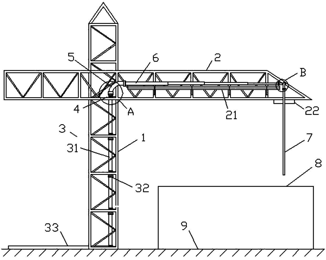
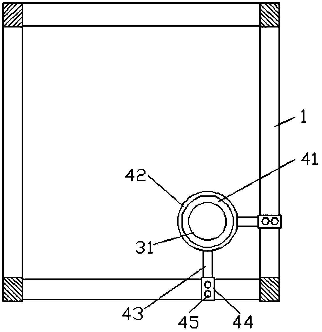
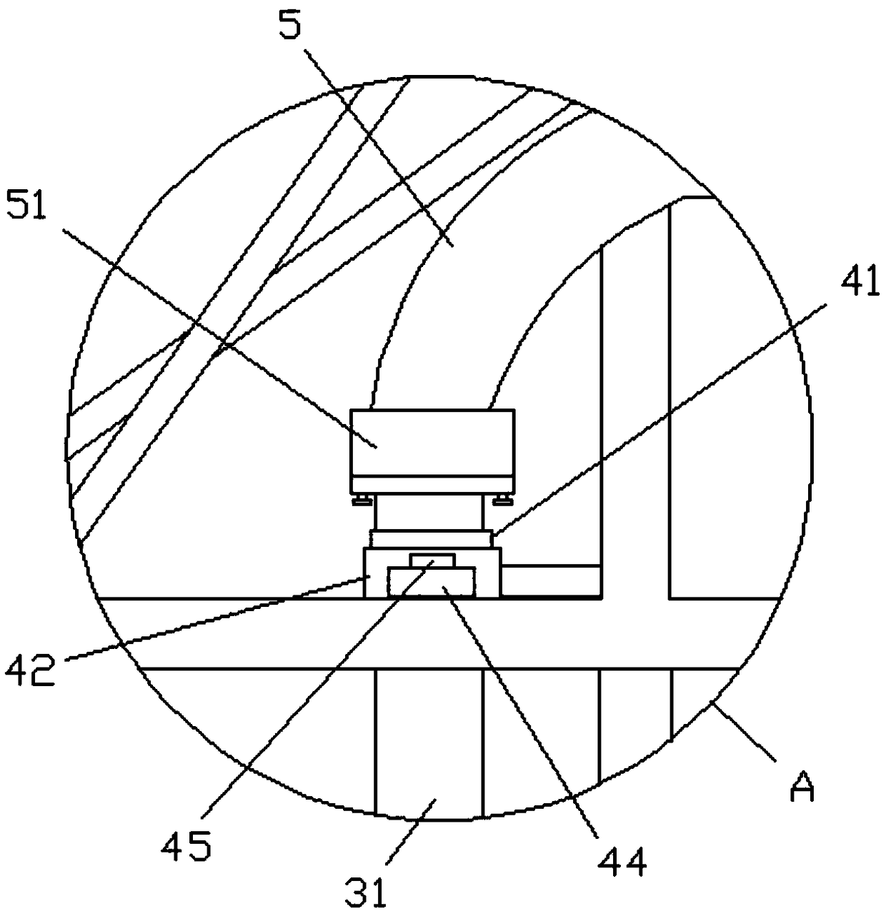
[0053] Such as Figure 1 to Figure 12 As shown, a conveying and pouring device based on high-rise building concrete construction, its structure includes a vertical conveying pipe 3 arranged in the tower crane standard section 1 and a horizontal conveying pipe 6 arranged on the side of the tower crane boom 2. The upper end of the conveying pipe 3 is connected to the left end of the horizontal conveying pipe 6 through a first elbow 5, and ...


PUM


Abstract

The invention relates to the field of concrete pouring equipment, and discloses a conveying and pouring device based on the concrete construction of a high-rise building. According to the conveying and pouring device based on the concrete construction of the high-rise building, high-rise concrete conveying pipelines are arranged on a tower crane standard section and a tower crane boom, and the length of each section of vertical pump pipes is consistent with the length of the tower crane standard section and increases at the same time. The conveying and pouring device has the characteristics ofsimple operation, flexible rotation and the like. The conveying and pouring device based on the concrete construction of the high-rise building structurally comprises a vertical conveying pipeline arranged in the tower crane standard section and a transverse conveying pipeline arranged on the side surface of the tower crane boom. The upper end part of the vertical conveying pipeline is connectedto the left end part of the transverse conveying pipeline through a first elbow, and rotating joints matched with the vertical conveying pipeline and the transverse conveying pipeline are arranged atthe two end part of the first elbow correspondingly. A shock absorption fixed assembly device matched with the tower crane standard section is arranged on the vertical conveying pipeline, and a supporting assembly matched with the transverse conveying pipeline is fixedly arranged on the side surface of the boom. The conveying and pouring device based on the concrete construction of the high-rise building is simple in operation and convenient to use, and is suitable for all kinds of building construction sites, especially for the construction of the high-rise building.

Description

Technical field [0001] The invention relates to the field of concrete pouring, in particular to a conveying and pouring device based on high-rise building concrete construction. Background technique [0002] At present, the concrete construction of high-rise buildings mainly uses fixed pumps and spreaders, assisted by tower cranes to complete the conveying and pouring of concrete. However, the following problems inevitably exist in the use of the above-mentioned machinery: [0003] 1. In large-area pouring, due to the limitation of the distributor itself, the material radius is small, which cannot meet the actual cloth range, and multiple distributors are required for cross pouring. In the blind area of ​​the pouring, the material is often cut from the same part of the pillar or shear wall. Until the concrete is poured, this will often cause excessive side pressure on the single-sided formwork, resulting in explosion or expansion; at the same time, because the concrete flows in th...

Claims


Application Information

Patent Timeline
IPC IPC(8): E04G21/02
CPCE04G21/02
Inventor 陈兴龙
Owner 陈兴龙
Why Eureka
Try Eureka