Anti-overpressure pressing device

A compression device and overpressure technology, which is applied in the direction of positioning device, clamping, support, etc., can solve the problems of surface damage, large noise when using the cylinder, waste of resources, etc., to avoid damage, improve the compression force, and improve The effect of processing efficiency

Inactive Publication Date: 2019-03-19
JIANGSU YUANHUA LIGHT CHEM EQUIP
View PDF5 Cites 2 Cited by
  • Summary
  • Abstract
  • Description
  • Claims
  • Application Information

AI Technical Summary

Problems solved by technology

[0002] In the existing equipment, it is more commonly used to set a vise on the workbench when processing workpieces, or to use cylinder clamps to clamp, and then process the workpiece. When using vises, it takes more time to clamp. When using a cylinder for fixing, continuous air supply is required to maintain the stability of the cylinder, which will cause a waste of resources, and the use of the cylinder in the workshop will cause a lot of noise, so it is necessary to design a fast and stable aluminum profile. fixture
[0003] In addition, due to the soft material of some workpieces, when positioning the workpiece, increasing the contact area between the force application surface and the surface of the workpiece, and at the same time making the pressure vertically applied to the surface of the workpiece can effectively ensure the compression effect of the workpiece. In addition, when When the clamping force is large, it will cause certain damage to the surface of the workpiece. Therefore, it is very necessary to design a fixture that is easy to adjust, can adapt to various workpieces, and can effectively control the clamping force at the same time. of

Method used


Image

  • Anti-overpressure pressing device
  • Anti-overpressure pressing device
  • Anti-overpressure pressing device

Examples


Embodiment Construction

[0016] The specific implementation manners of the present invention will be described in further detail below in conjunction with the accompanying drawings.

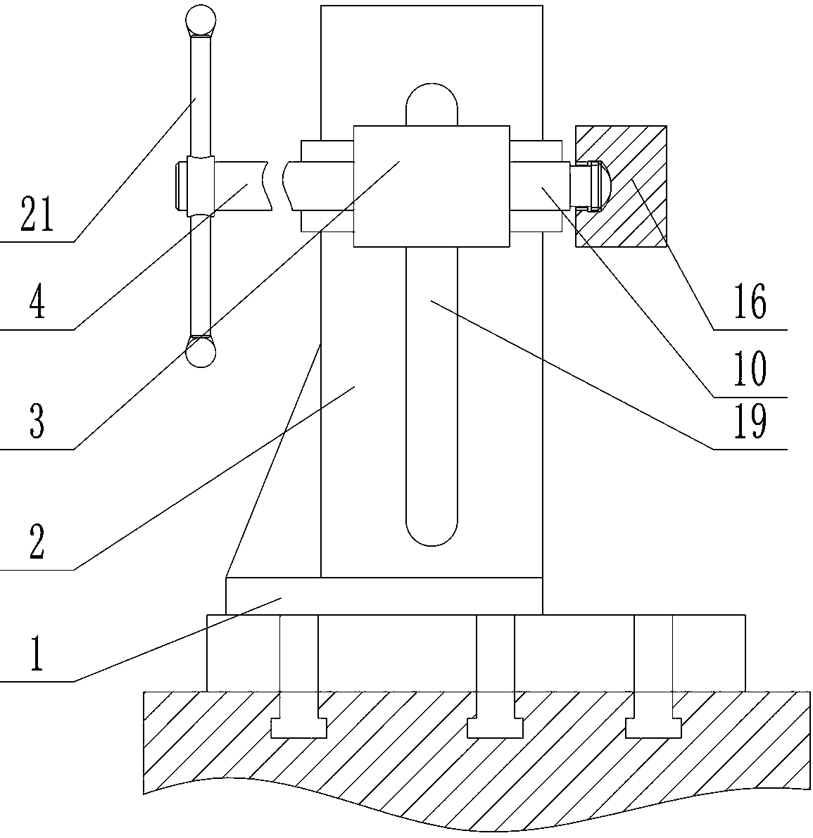
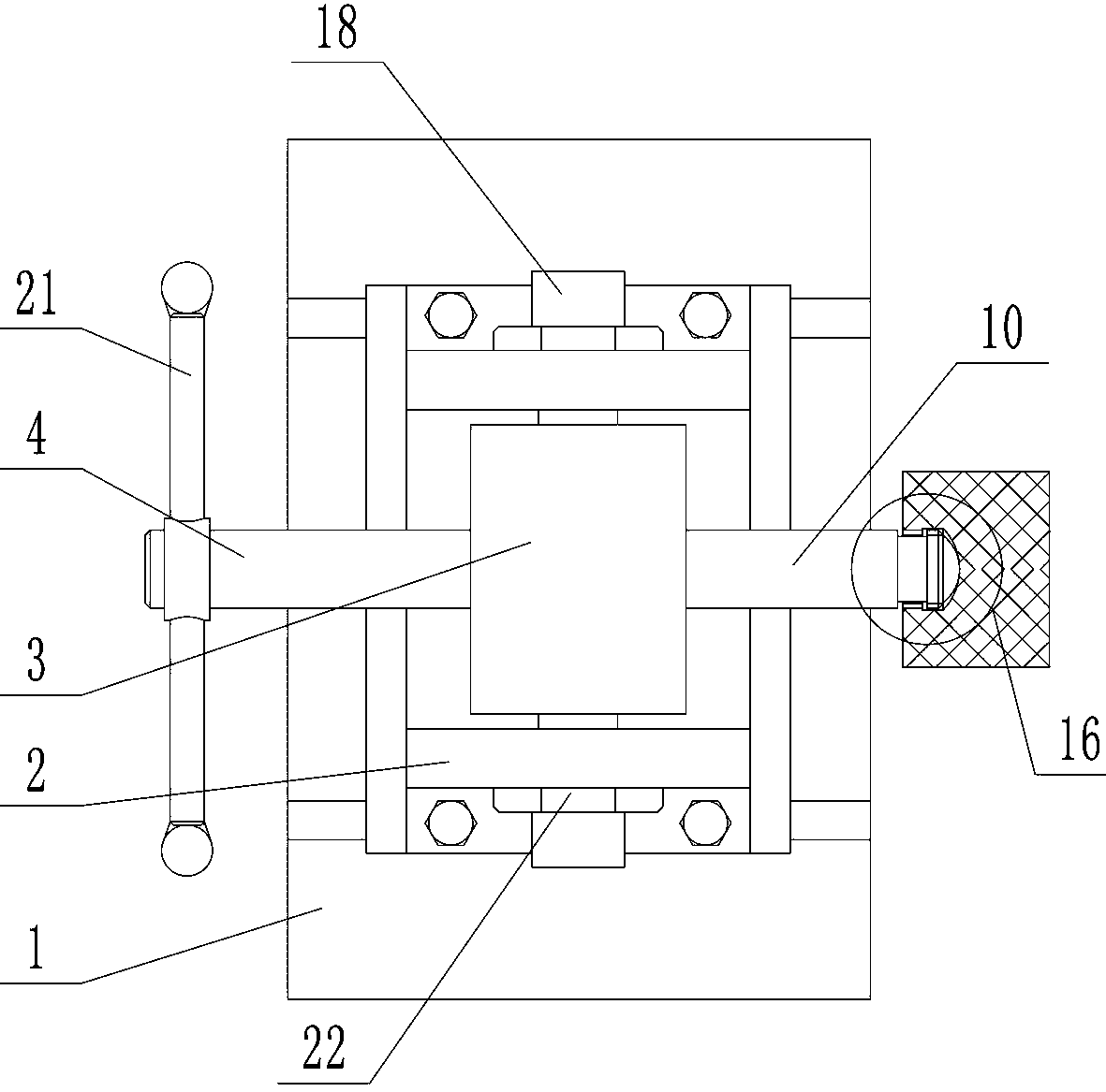
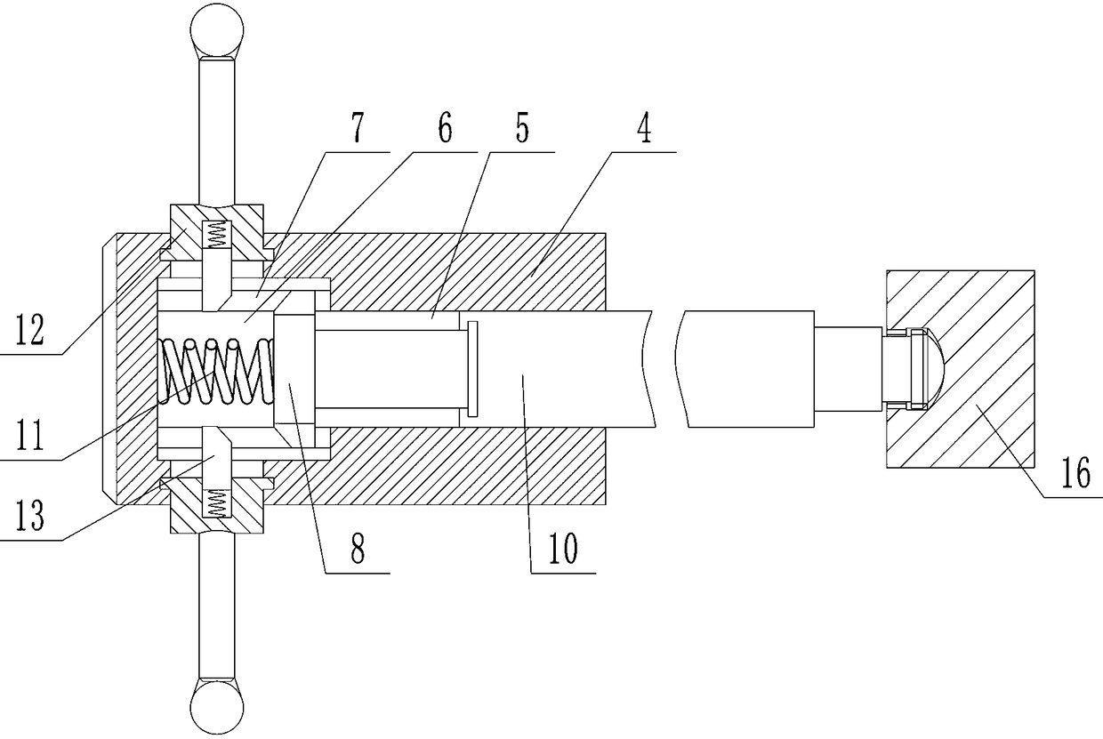
[0017] Depend on Figure 1-8 It can be seen that the present invention includes a horizontally placed base plate 1, two vertical guide plates 2 placed in parallel front and back are provided above the base plate 1, and a slider 3 that can move up and down along the guide plate 2 is provided between the two guide plates 2. The left and right end surfaces of the slider 3 are interspersed with screw rods 4, and the screw rod 4 and the slider 3 are threadedly connected. The mounting hole 6 connected to the hole 5, the diameter of the mounting hole 6 is greater than the diameter of the blind hole 5, the side wall of the mounting hole 6 is provided with axially distributed and circumferentially uniform chute 7, the mounting hole 6 is provided with a Slide the movable disc 8 left and right in the hole 6, and the outer edge of ...


PUM


Abstract

The invention discloses an anti-overpressure pressing device. Positioning and pressing of workpieces are well achieved, the pressing force to the workpieces can be well controlled, damage to the workpieces is avoided, and the effect of improving the processing efficiency for mass production is achieved. According to the technical scheme, the pressing device comprises a sliding block; a screw is inserted in the sliding block; a mounting hole is formed in the screw; a sliding groove is formed in the side wall of the mounting hole; a movable plate is arranged in the mounting hole; a convex blockis arranged on the movable plate; an ejector rod is inserted in a blind hole; an annular sleeve is mounted on the outer edge of the screw in a clamped mode; an inner hole of the annular sleeve is provided with a clamping block; and the annular sleeve can drive the screw to rotate through the clamping block during rotating, the movable plate moves rightwards and jacks the clamping block upwards through the convex block, a groove is formed in one side surface of one end of the outer side of the sliding groove, the highest point of the convex block is flush with the lowest point of the groove, the annular sleeve can only drive the screw to rotate unidirectionally during rotation under the action of the groove when the clamping block is jacked upwards through the convex block, and the screw can only move leftwards due to unidirectional rotation of the screw. The pressing device is novel in conception.

Description

technical field [0001] The invention relates to the technical field of clamps for machining, in particular to a compression device for preventing overpressure. Background technique [0002] In the existing equipment, it is more commonly used to set a vise on the workbench, or use a cylinder clamp to clamp, and then process the workpiece. When using a vise, it takes more time to clamp. When using a cylinder for fixing, continuous air supply is required to maintain the stability of the cylinder, which will cause a waste of resources, and the use of the cylinder in the workshop will cause a lot of noise, so it is necessary to design a fast and stable aluminum profile. fixture. [0003] In addition, due to the soft material of some workpieces, when positioning the workpiece, increasing the contact area between the force application surface and the surface of the workpiece, and at the same time making the pressure vertically applied to the surface of the workpiece can effectivel...

Claims


Application Information

Patent Timeline
Patent Type & Authority Applications(China)
IPC IPC(8): B23Q3/06
CPCB23Q3/06
Inventor 田长江白冉马博黄卫刘维桢
Owner JIANGSU YUANHUA LIGHT CHEM EQUIP
Why Eureka
Try Eureka