A kind of electrified ice melting system and its ice melting method

An ice-melting method and ice-melting technology, applied in the installation of electrical components, cables, overhead installation, etc., can solve the problems of line power failure and ice-melting, and achieve the effect of improving the anti-icing ability.

Active Publication Date: 2021-01-26
HUNAN XIANGDIAN POWER TEST & RES TECH LTD
View PDF6 Cites 0 Cited by
  • Summary
  • Abstract
  • Description
  • Claims
  • Application Information

AI Technical Summary

Problems solved by technology

[0005] The embodiment of the present invention provides a live ice-melting system, which aims to solve the impact caused by the power outage and ice-melting of the line in the prior art, so as to achieve the problem of uninterrupted power-off ice-melting

Method used


Image

  • A kind of electrified ice melting system and its ice melting method
  • A kind of electrified ice melting system and its ice melting method
  • A kind of electrified ice melting system and its ice melting method

Examples


Embodiment 1

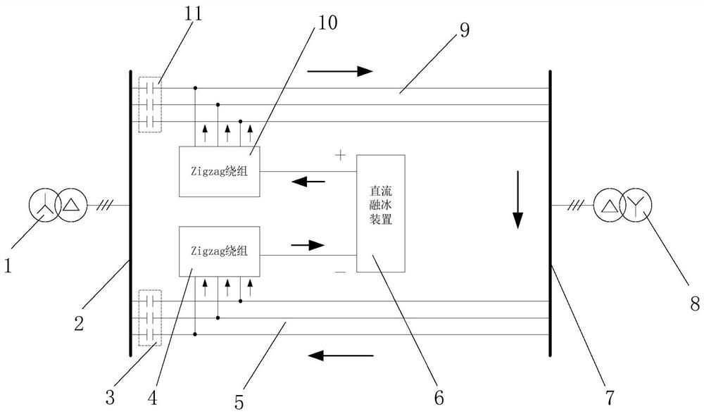
[0042] see figure 1 , which is a structural schematic diagram of an electrified ice-melting system provided in the embodiment of the present application.

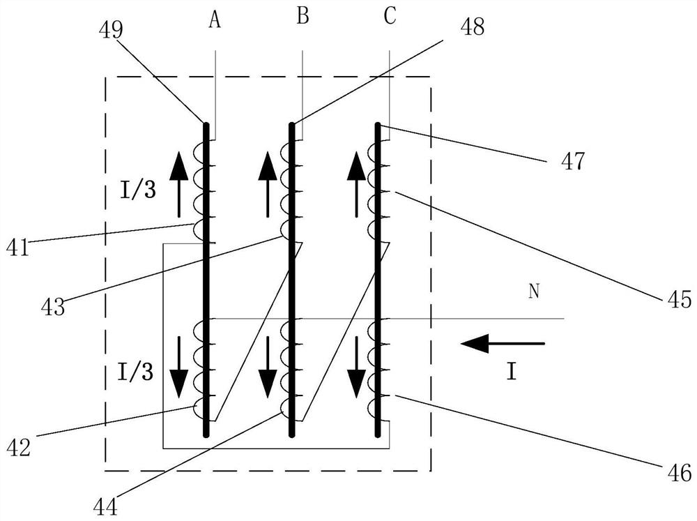
[0043] Such as figure 1 As shown, the electrified ice melting system includes a first DC blocking device 3 , a second DC blocking device 11 , a first Zigzag winding 4 , a second Zigzag winding 10 and a DC ice melting device 6 . The first DC blocking device 3 and the second DC blocking device 11 are respectively connected in series on the return line between two main transformer busbars, and the two main transformers are the main transformer 1 of station A and the main transformer 2 of station B respectively. Among them, the main transformer 1 of station A is connected to the bus bar 2 of station A, the main transformer 1 of station B is connected to the bus bar 7 of station B, and the bus bar 2 of station A and the bus bar 7 of station B are connected in series through the first line 5 and the second line 9 to form return...

Embodiment 2

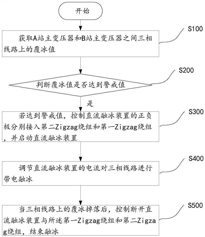
[0057] The embodiment of the present application also provides a charging ice-melting method, which is applied to the charging ice-melting system provided in the first embodiment. see image 3 , is a schematic flow chart of a charging ice-melting method provided in the embodiment of the present application.

[0058] In step S100, the icing value on the three-phase line between the main transformer of station A and the main transformer of station B is acquired.

[0059] During the specific implementation process, a surveillance camera can be installed on the three-phase line between the main transformer of station A and the main transformer of station B, or a real-time picture of the three-phase line can be taken by a drone. The pictures are compared to calculate the icing value. Specifically, how to calculate the above-mentioned method of the ice-covering value can refer to the calculation of the ice-covering value in the prior art, and will not be elaborated here.

[0060]...


PUM


Abstract

The invention provides an electric ice melting system and an ice melting method thereof. The electric ice melting system comprises a first blocking device, a second blocking device, a first Zigzag winding, a second Zigzag winding, and a direct current ice melting device, wherein the first blocking device and the second blocking device are respectively connected in series on a return line between two main transformer bus bars; a positive pole of the direct current ice melting device is connected to an input side of the second Zigzag winding, and output sides of the second Zigzag winding are respectively connected to three-phase electric wires on one side of the return line; a negative pole of the direct current ice melting device is connected to an output side of the first Zigzag winding, and input sides of the first Zigzag winding are respectively connected to three-phase electric wires on the other side of the return line. The electric ice melting system can melt ice with electricity,and there is no need to power off and queue up to melt ice. The direct current ice melting device has much applicability and is easy to promote and use, and the current is not limited in size, and the access device occupies a small area and has low cost.

Description

technical field [0001] The invention belongs to the technical field of electrical engineering, and in particular relates to an electrified ice-melting system and an ice-melting method thereof. Background technique [0002] In recent years, rain, snow and freezing disasters have occurred frequently in the southern region, which has seriously affected the operation of the power grid. Current ice melting is currently the most direct and effective measure to deal with grid ice disasters. However, the existing ice-melting methods are all power-off ice-melting methods. On the one hand, the power outage of the line will cause a large number of users to limit power, which will affect the quality service. Ice melting must be carried out sequentially, so that if the ice melting is not timely, the line still has the risk of falling down and breaking the line. Therefore, there are still many technical defects in the practical application of the power failure ice melting method. [00...

Claims


Application Information

Patent Timeline
Patent Type & Authority Patents(China)
IPC IPC(8): H02G7/16
Inventor 陆佳政朱远谭艳军朱思国黄清军毛新果
Owner HUNAN XIANGDIAN POWER TEST & RES TECH LTD
Why Eureka
Try Eureka