
Novel live ice melting device and ice melting method thereof

A new type of ice-melting technology, applied in cable installation, electrical components, overhead installation, etc., can solve problems affecting system protection, difficulty in practical promotion, and difficulty in developing high-frequency excitation sources, achieving high reliability and simple use Convenience and the effect of improving ice resistance

Inactive Publication Date: 2019-11-29
STATE GRID HUNAN ELECTRIC POWER +2
View PDF4 Cites 1 Cited by
  • Summary
  • Abstract
  • Description
  • Claims
  • Application Information

AI Technical Summary

Problems solved by technology

At present, some scientific research institutes have proposed several live ice melting methods. The ice melting method based on load current transfer transfers the load of multi-split conductors to one sub-conductor to achieve ice melting, but it is only applicable to lines with 4 splits and above. The electrified ice-melting method of excitation is difficult to develop high-frequency excitation sources, and it is difficult to promote it in practice. Other electrified ice-melting methods generally have many problems such as the inability to effectively connect the ice-melting power supply, and the DC voltage will affect system protection and measurement during ice melting.

Method used


Image

  • Novel live ice melting device and ice melting method thereof
  • Novel live ice melting device and ice melting method thereof
  • Novel live ice melting device and ice melting method thereof

Examples


Embodiment Construction

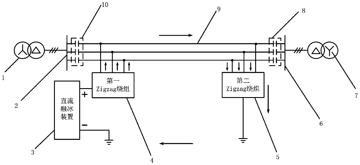
[0022] Such as figure 1 Shown is the application schematic diagram of the device of the present invention: below in conjunction with a specific embodiment, the device of the present invention is described:

[0023] The figure includes the main transformer (main transformer) 1 of station A, the bus bar of station A 2, the DC ice melting device 3, the first Zigzag winding 4, the second Zigzag winding 5, the bus bar of station B 6, the main transformer of station B 7, the second isolation Straight device 8, circuit to be melted ice 9 and the first straight blocking device 10;

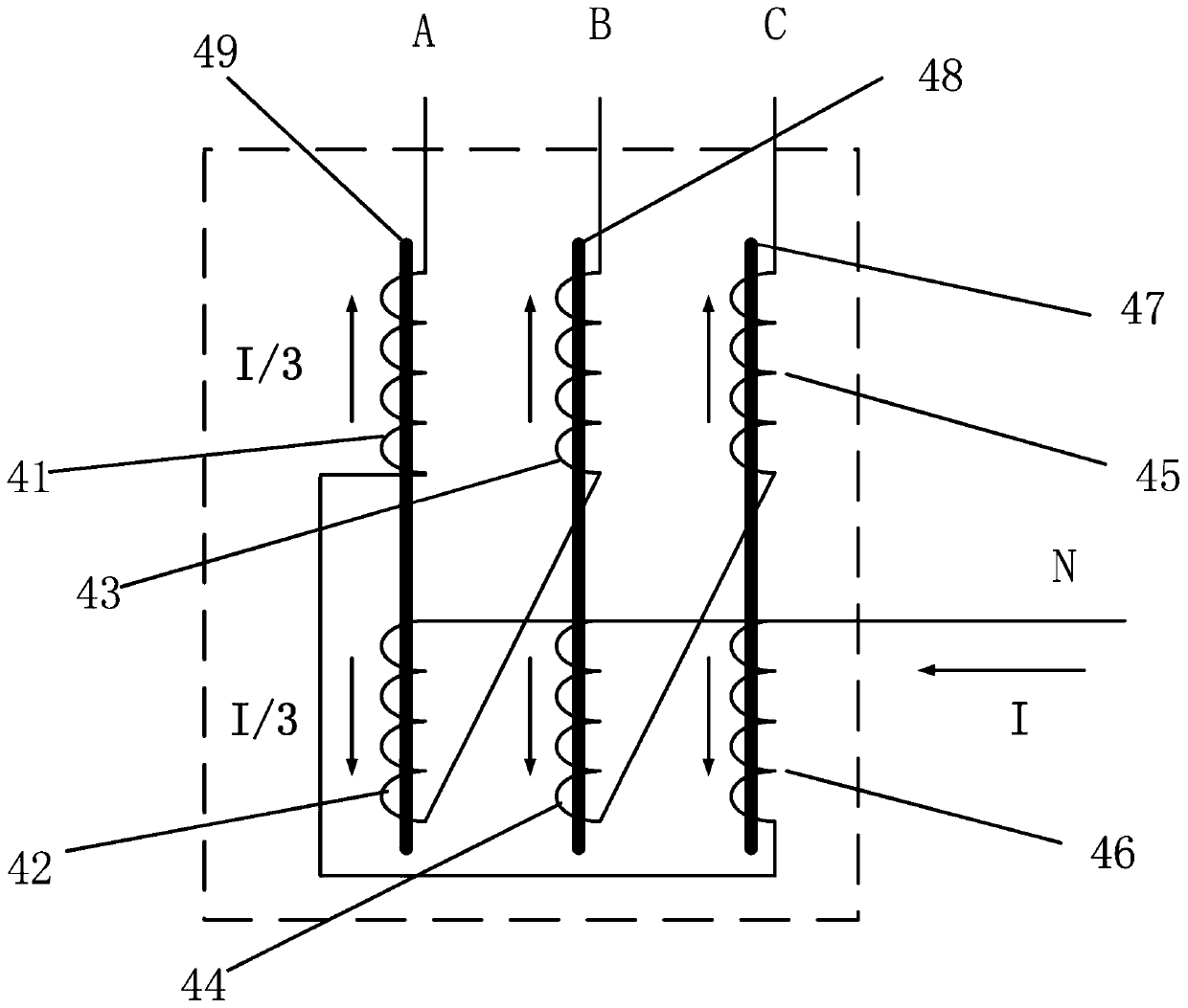
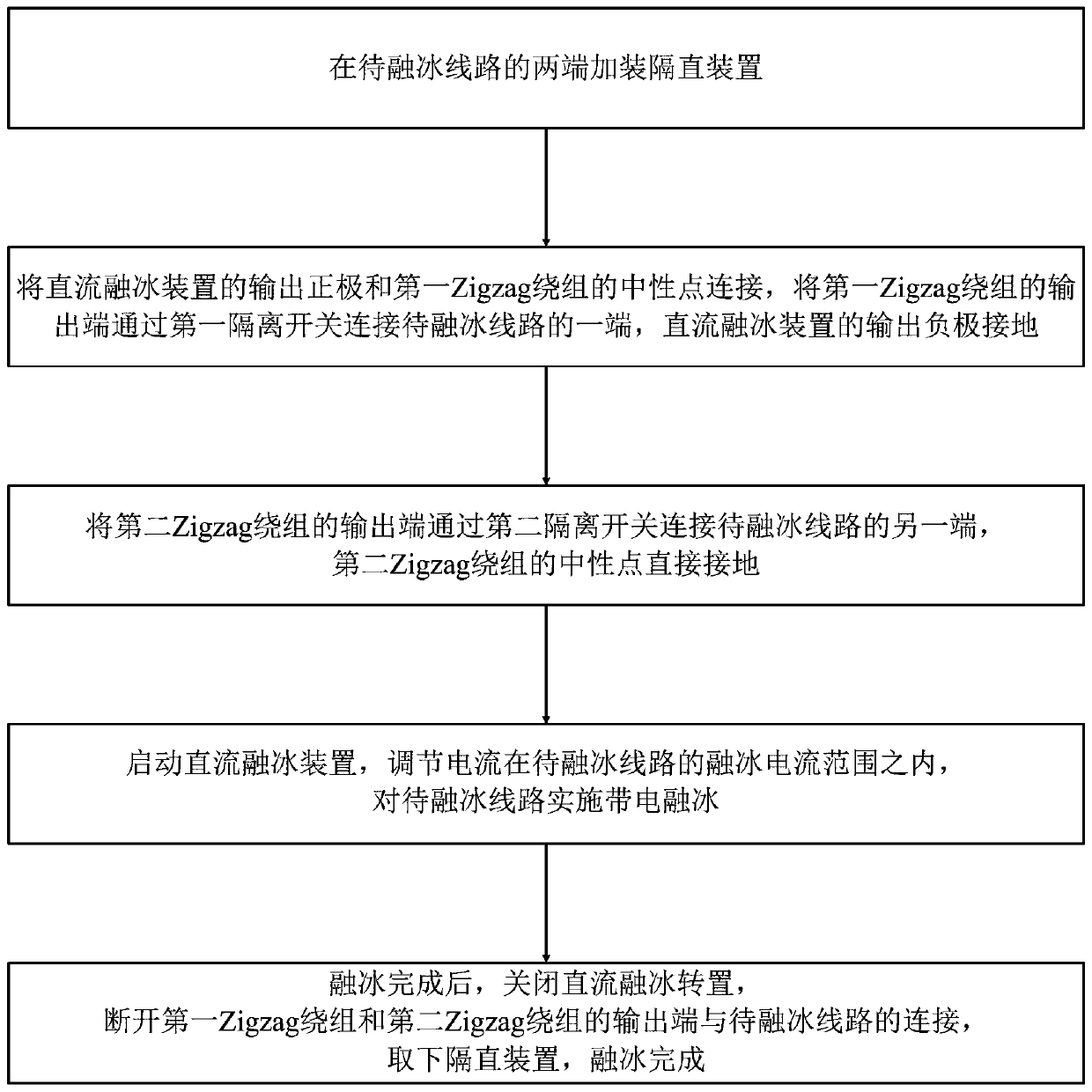
[0024] In specific applications, the first DC blocking device and the second DC blocking device are installed at both ends of the line to be ice-melted to isolate the ice-melting DC power loaded on the line to be ice-melted; the positive output terminal of the DC ice-melting device is connected to The neutral point of the first Zigzag winding, the negative pole of the DC ice melting device is directly gro...


PUM


Abstract

The invention discloses a novel live ice melting device which comprises a DC blocking device, a DC ice melting device, a first Zigzag winding and a second Zigzag winding. The DC blocking device is installed at the two ends of a line under ice melting and isolates the ice melting direct current loaded on the line under ice melting. The positive output end of the DC ice melting device is connected with the neutral point of the first Zigzag winding, and the negative electrode of the DC ice melting device is directly grounded. The output end of the first Zigzag winding is connected with one end ofthe line under ice melting. The output end of the second Zigzag winding is connected with the other end of the line under ice melting, and the neutral point of the second Zigzag winding is directly grounded. The invention also discloses an ice melting method of the novel live ice melting device. The live ice melting can be realized for any loop, the line does not lose power during ice melting, the modification of the line during ice melting is minimal, protection, control and stability of the AC system are basically not affected, the reliability is high and the use is simple and convenient.

Description

technical field [0001] The invention specifically relates to a novel electrified ice-melting device and an ice-melting method thereof. Background technique [0002] With the development of economy and technology, electric energy has become an indispensable secondary energy source in people's production and life, bringing endless convenience to people's production and life. With the increasingly prominent environmental problems, the frequent occurrence of extreme weather has also brought great challenges to the stable and reliable operation of the power system. [0003] In recent years, rain, snow and freezing disasters have occurred frequently in the southern region, which has seriously affected the operation of the power grid. Current ice melting is currently the most direct and effective measure to deal with grid ice disasters. However, the existing ice-melting methods are all power-off ice-melting methods. On the one hand, the power outage of the line will cause a large...

Claims


Application Information

Patent Timeline
Patent Type & Authority Applications(China)
IPC IPC(8): H02G7/16
CPCH02G7/16
Inventor 陆佳政朱远李波谭艳军朱思国毛新果
Owner STATE GRID HUNAN ELECTRIC POWER
Learn More