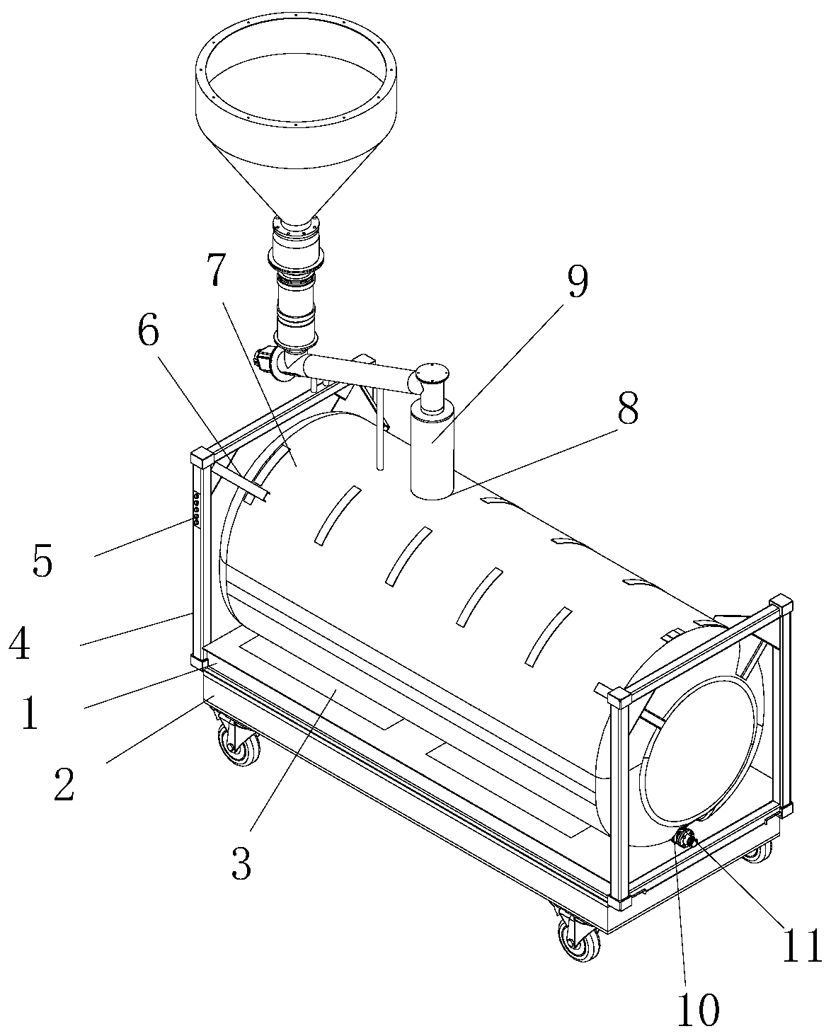
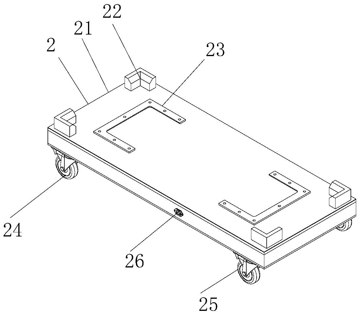
[0009] The present invention provides a transport tank for chemical production through improvement. When the transport tank needs to be moved to the position where it needs to work, it is difficult to move due to its large volume. A moving device is provided at the bottom of the bottom plate. The charging port is connected to the power supply through the
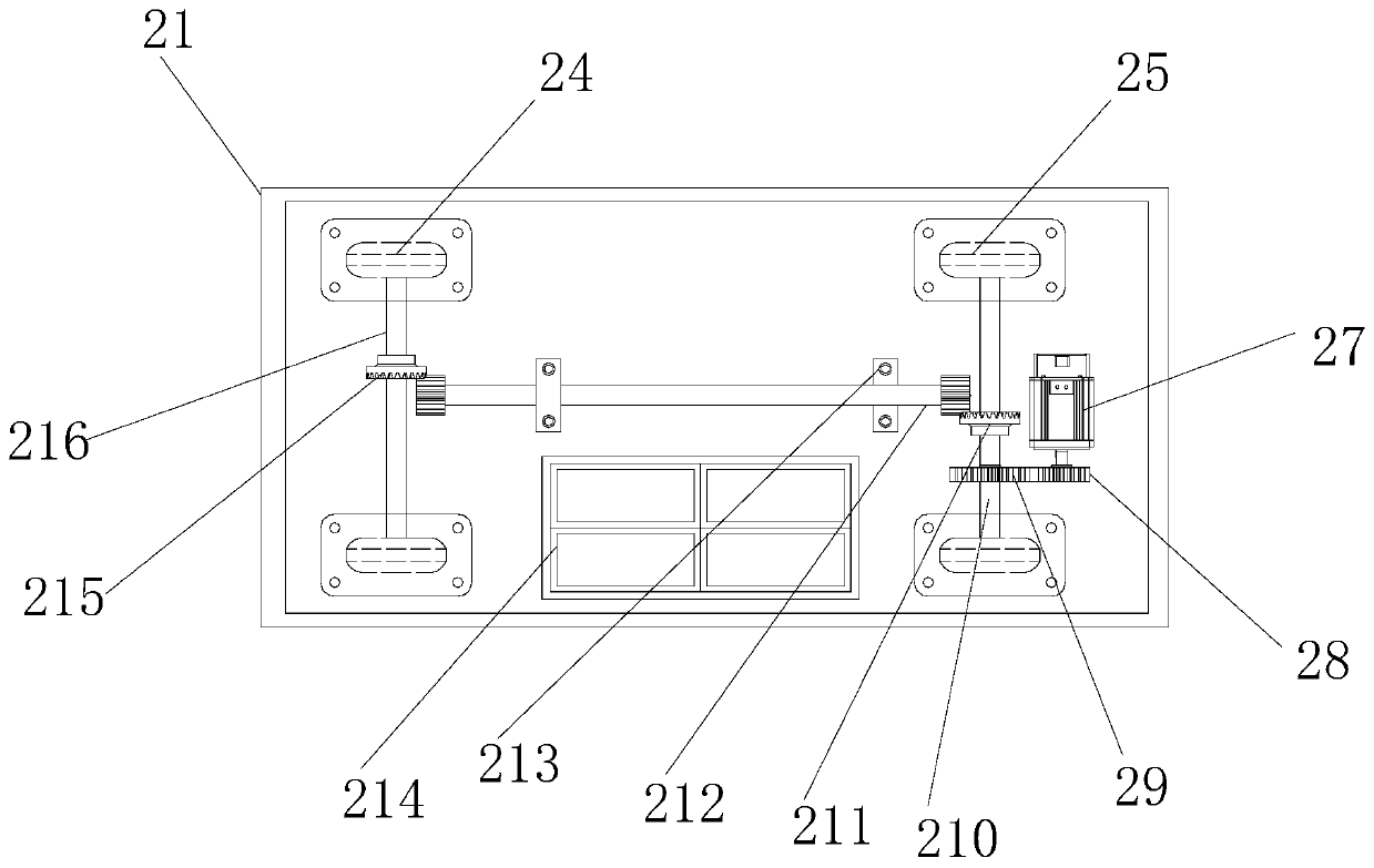
power cord to charge the battery in the main body and provide the required power for the equipment to work. Then the equipment can be controlled through the control button on the controller, and then the first motor on the right side of the main body is started. , the output shaft at the front end of the first motor starts to rotate, and then drives the driving gear to start rotating, then the left end of the driving gear drives the driven gear to rotate, and then the driven gear can make the first transmission rod rotate, when the first transmission rod rotates, the rear wheel is It can be rotated. The middle part of the outer
diameter surface of the first transmission rod drives the gear rod to rotate through the first toothed plate. The left and right ends of the outer
diameter surface of the gear rod pass through the shaft seat. The gear plate makes the second transmission rod rotate, and then the front and rear ends of the second transmission rod can make the front wheel rotate, and realize the electric movement of the front wheel and the rear wheel. The control button on the controller can stop and stop the
mobile device immediately. Start to solve the problem of poor mobile convenience due to its
large size during the moving process; during the moving process, it is easy to generate vibration, affect the
storage tank, and be easily damaged. There is a shock absorbing device in the bottom plate, and the upper end of the seat There is a mounting plate, and the top of the mounting plate is connected and installed with the
storage tank. Six sets of first springs are evenly distributed at the left and right ends of the bottom of the mounting plate, which can effectively offset the vibration generated. There is a
piston in the middle of the bottom of the mounting plate. There is a pressure rod on the top, which is used to press down the pressure rod when vibration occurs. A second spring is provided on the outer
diameter surface of the pressure rod. The second spring can be compressed in the circular groove, and then the pressure rod can be inserted into the upper end of the support rod. Buffering is to quickly offset the vibration. The bottom of the first steel plate is bonded with a foam layer and a
silicone layer. Both have good
energy absorption and
cushioning properties. The
storage tank is protected, which solves the problems of poor stability, easy to affect material transportation, and easy damage to the tank during the movement; when chemical raw materials need to be injected into the storage tank, solids or unevenness are likely to exist inside At the same time, a pretreatment device is installed on the top of the protective frame, and the raw materials are poured from the feeding hopper on the top of the pretreatment device, then pass through the first connecting pipe and the second connecting pipe at the bottom, and finally enter the conveying pipe from the feeding pipe, and then Start the second motor by the control button on the controller to start working, the output shaft on the right side of the second motor starts to rotate, and then drives the
auger to start working, and then drives the raw materials in the conveying pipe to be conveyed by screw and conveyed to the
discharge pipe Then it is discharged into the inlet and outlet from the third connecting pipe at the bottom, and finally reaches the storage tank for storage to complete the injection work, which solves the problems of solids, unevenness and poor pretreatment effect when feeding.

