A transport tank for chemical production

A technology for chemical production and conveying tanks, which is applied in the field of chemical machinery and can solve the problems of difficult movement, large volume, and easy damage.

Active Publication Date: 2021-04-02
山东鼎泰新能源有限公司
View PDF10 Cites 0 Cited by
  • Summary
  • Abstract
  • Description
  • Claims
  • Application Information

AI Technical Summary

Problems solved by technology

[0009] The present invention provides a transport tank for chemical production through improvement. When the transport tank needs to be moved to the position where it needs to work, it is difficult to move due to its large volume. A moving device is provided at the bottom of the bottom plate. The charging port is connected to the power supply through the power cord to charge the battery in the main body and provide the required power for the equipment to work. Then the equipment can be controlled through the control button on the controller, and then the first motor on the right side of the main body is started. , the output shaft at the front end of the first motor starts to rotate, and then drives the driving gear to start rotating, then the left end of the driving gear drives the driven gear to rotate, and then the driven gear can make the first transmission rod rotate, when the first transmission rod rotates, the rear wheel is It can be rotated. The middle part of the outer diameter surface of the first transmission rod drives the gear rod to rotate through the first toothed plate. The left and right ends of the outer diameter surface of the gear rod pass through the shaft seat. The gear plate makes the second transmission rod rotate, and then the front and rear ends of the second transmission rod can make the front wheel rotate, and realize the electric movement of the front wheel and the rear wheel. The control button on the controller can stop and stop the mobile device immediately. Start to solve the problem of poor mobile convenience due to its large size during the moving process; during the moving process, it is easy to generate vibration, affect the storage tank, and be easily damaged. There is a shock absorbing device in the bottom plate, and the upper end of the seat There is a mounting plate, and the top of the mounting plate is connected and installed with the storage tank. Six sets of first springs are evenly distributed at the left and right ends of the bottom of the mounting plate, which can effectively offset the vibration generated. There is a piston in the middle of the bottom of the mounting plate. There is a pressure rod on the top, which is used to press down the pressure rod when vibration occurs. A second spring is provided on the outer diameter surface of the pressure rod. The second spring can be compressed in the circular groove, and then the pressure rod can be inserted into the upper end of the support rod. Buffering is to quickly offset the vibration. The bottom of the first steel plate is bonded with a foam layer and a silicone layer. Both have good energy absorption and cushioning properties. The storage tank is protected, which solves the problems of poor stability, easy to affect material transportation, and easy damage to the tank during the movement; when chemical raw materials need to be injected into the storage tank, solids or unevenness are likely to exist inside At the same time, a pretreatment device is installed on the top of the protective frame, and the raw materials are poured from the feeding hopper on the top of the pretreatment device, then pass through the first connecting pipe and the second connecting pipe at the bottom, and finally enter the conveying pipe from the feeding pipe, and then Start the second motor by the control button on the controller to start working, the output shaft on the right side of the second motor starts to rotate, and then drives the auger to start working, and then drives the raw materials in the conveying pipe to be conveyed by screw and conveyed to the discharge pipe Then it is discharged into the inlet and outlet from the third connecting pipe at the bottom, and finally reaches the storage tank for storage to complete the injection work, which solves the problems of solids, unevenness and poor pretreatment effect when feeding.

Method used


Image

  • A transport tank for chemical production
  • A transport tank for chemical production
  • A transport tank for chemical production

Examples


Embodiment Construction

[0040] The following will be combined with Figure 1-7 The present invention is described in detail, and the technical solutions in the embodiments of the present invention are clearly and completely described. Apparently, the described embodiments are only some of the embodiments of the present invention, not all of them. Based on the embodiments of the present invention, all other embodiments obtained by persons of ordinary skill in the art without making creative efforts belong to the protection scope of the present invention.

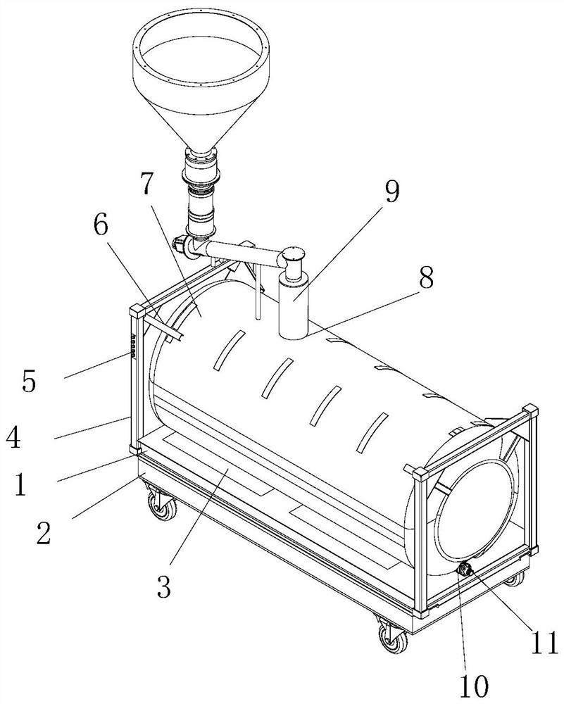
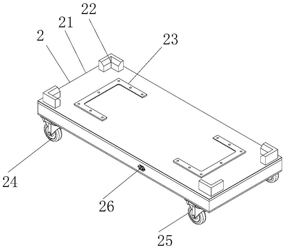
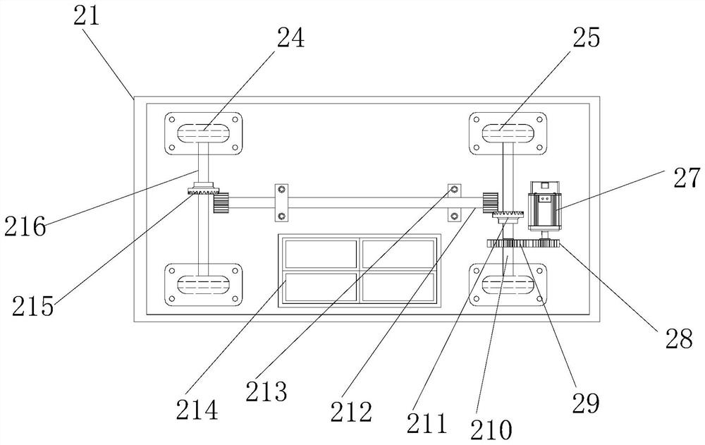
[0041] The present invention provides a transport tank for chemical production through improvement, including a bottom plate 1, a protective frame 4, a controller 5, a fixing member 6, a storage tank 7, an injection port 8, a discharge pipe 10, a ball valve 11, a moving device 2, The shock absorbing device 3 and the pretreatment device 9, the bottom of the base plate 1 is provided with a mobile device 2, the left and right ends of the base plate 1 a...


PUM


Abstract

The invention discloses a conveying tank for chemical industry production. The conveying tank for the chemical industry production comprises a bottom plate, a protecting frame, a controller, a movingdevice, a damping device and a pre-treating device. Due to that chemical raw materials are poured into a storing tank, and solids are easily formed in the chemical raw materials or the chemical raw materials are not uniform, the pre-treating device is arranged on the top part of the protecting frame; the raw materials are filled through a feeding bucket on the top part of the pre-treating device and then pass through a first connecting pipe and a second connecting pipe at the bottom part, and finally the materials enter a conveying pipe through a feeding pipe; a second motor is started to workthrough a control button on the controller; an output shaft at the right side of the second motor starts rotating, and an auger is driven to start working; the raw materials in the conveying pipe aredriven to spirally convey to a discharging pipe; the raw materials are discharged into a filling port through a third connecting pipe and finally enter the storing tank for storing, and thus the filling work is finished, and the problems that solids are formed during feeding, the raw materials are not uniform and the pre-treating effect is poor can be solved.

Description

technical field [0001] The invention relates to the related fields of chemical machinery, in particular to a transport tank for chemical production. Background technique [0002] Chemical industry is the abbreviation of "chemical technology", "chemical industry", "chemical engineering", etc. Any technology that uses chemical methods to change the composition and structure of substances or synthesize new substances belongs to chemical production technology, that is, chemical technology. Known as chemicals or chemical products, many chemical raw materials are used in chemical industry. These raw materials are solid or liquid, and special transfer tanks are required for storage or transportation when raw materials are stored. [0003] However, the existing transfer tanks for chemical production have the following problems: [0004] 1. The existing transport tanks for chemical production are not easy to move due to their large volume during the moving process. [0005] 2. The ...

Claims


Application Information

Patent Timeline
Patent Type & Authority Patents(China)
IPC IPC(8): B65D88/06B65D90/12B65D90/18B65D90/00
Inventor 韩天信
Owner 山东鼎泰新能源有限公司
Why Eureka
Try Eureka