Anti-backflow bottom valve of plastic mixed-flow pump

A mixed-flow pump and anti-backflow technology, which is applied to pumps, parts of pumping devices for elastic fluids, control valves, etc., can solve problems such as reducing the service life of valve cores

Inactive Publication Date: 2021-05-04
潘连山
View PDF11 Cites 0 Cited by
  • Summary
  • Abstract
  • Description
  • Claims
  • Application Information

AI Technical Summary

Problems solved by technology

At present, after the water pump stops working, the water flow quickly falls back, causing the valve core to fall rapidly and hit the water inlet

Method used


Image

  • Anti-backflow bottom valve of plastic mixed-flow pump
  • Anti-backflow bottom valve of plastic mixed-flow pump
  • Anti-backflow bottom valve of plastic mixed-flow pump

Examples


Embodiment 1

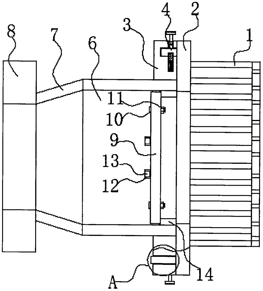
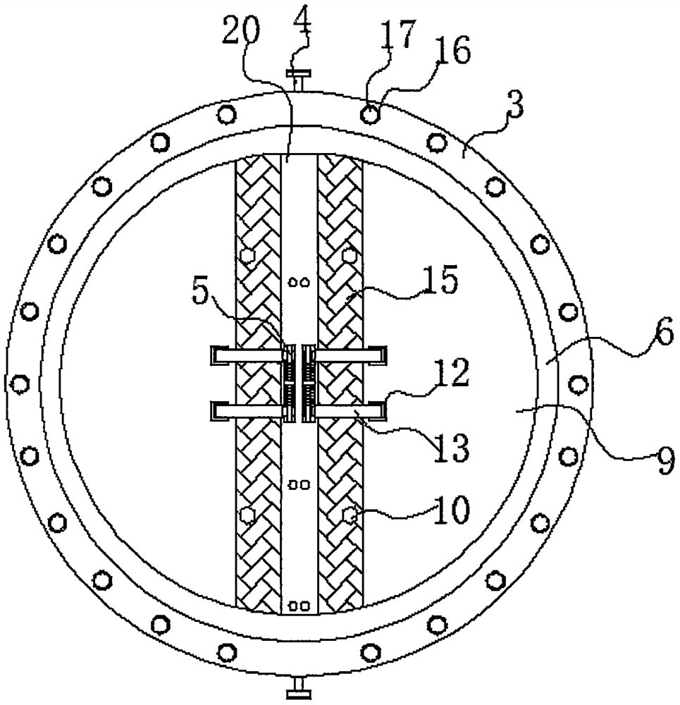
[0021] refer to Figure 1-2 , a plastic mixed flow pump anti-reflux bottom valve, comprising a connecting pipe 6, one end of the connecting pipe 6 is connected with a funnel pipe 7, one end of the funnel pipe 7 is connected with a flange 8, and the other end of the connecting pipe 6 is connected with a protection mechanism, the protection mechanism can The water pump is protected, the inner side of the connecting pipe 6 is fixed with a limit ring plate 14, and the middle of the inner side of the connecting pipe 6 on the side of the limit ring plate 14 is fixed with a fixed plate 20, and both sides of the fixed plate 20 are rotatably connected with a waterproof cloth 15 , one side of the waterproof cloth 15 is fixed with a valve flap 9, and both sides of the valve flap 9 are provided with bolts 10, one end of the bolt 10 passes through the waterproof cloth 15 and the valve flap 9 and is connected with a nut 11, and both sides of the valve flap 9 are fixed with Connecting slot p...

Embodiment 2

[0023] refer to figure 1 , as another preferred embodiment of the present invention, the difference from Embodiment 1 is that the protection mechanism includes a connecting ring plate 2 and a side ring plate 3, the side ring plate 3 is fixed outside one end of the connecting pipe 6, and one side of the connecting ring plate 2 The protective cover 1 is fixed, and the connecting ring plate 2 is set on the side of the side ring plate 3, and the upper and lower sides between the side ring plate 3 and the connecting ring plate 2 are connected by the limit mechanism 4, and the protective cover 1 can prevent the water pump from entering the water pump. The water is filtered once, so that the sundries in the water will not be sucked into the water pump and the valve core, which protects the rotor of the water pump and prevents the turbine and valve core from being damaged.

Embodiment 3

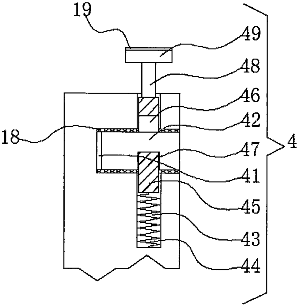
[0025] refer to image 3 , as another preferred embodiment of the present invention, the difference from Embodiment 1 is that the limiting mechanism 4 includes a slot 41 and a groove 43, the groove 43 is provided around the base plate 1, and the slot 41 is provided above the base plate 1 At the four corners, and connected with the groove 43, the inner wall of the slot 41 is fixed with a rubber pad 18, and the four corners of the bottom of the bracket 2 are fixed with inserting rods 42, and the inserting rods 42 are inserted in the slot 41, and the inserting rods 42- Limiting groove 47 is offered on the side, and baffle plate 45 is inserted in the groove 43, and limiting hole 46 is offered on the baffle plate 45, and the sidewall of limiting hole 46 is inserted in the limiting groove 47, and baffle plate 45 both sides A spring 44 is fixed, one end of the spring 44 is fixed at the bottom of the groove 43, a connecting rod 48 is fixed on one side of the baffle plate 45, one end o...


PUM


Abstract

The invention relates to the technical field of bottom valves, in particular to an anti-backflow bottom valve of a plastic mixed-flow pump. The anti-backflow bottom valve comprises a connecting pipe, one end of the connecting pipe is connected with a funnel pipe, one end of the funnel pipe is connected with a flange, the other end of the connecting pipe is connected with a protection mechanism, a limiting ring plate is fixed to one side in the connecting pipe, a fixed plate is fixed to the middle of one side of the position, on one side of the limiting ring plate, in the connecting pipe, waterproof cloth is rotationally connected to the two sides of the fixed plate, a valve clack is fixed to one side of the waterproof cloth, bolts are arranged on the two sides of the valve clack, one end of each bolt penetrates through the waterproof cloth and the valve clack and is connected with a nut, connecting groove plates are fixed to the two sides of the valve clack, and a rotating rod is rotationally connected in each connecting groove plate. According to the anti-backflow bottom valve, a water pump can be protected through a protection cover, water entering the water pump can be filtered once through the protection cover, impurities in the water cannot be sucked into the water pump and a valve element, and a rotor of the water pump is protected.

Description

technical field [0001] The invention relates to the technical field of bottom valves, in particular to a plastic mixed-flow pump anti-backflow bottom valve. Background technique [0002] The bottom valve, also known as the check valve, is a low-pressure flat valve. Its function is to ensure that the liquid flows in one direction in the suction pipe, so that the pump can work normally. When the pump stops working for a short time, the liquid cannot return to the water source tank, ensuring The suction pipe is filled with liquid to facilitate the starting of the pump. The bottom valve is an energy-saving valve, which is generally installed at the bottom of the underwater suction pipe of the water pump, and is used to limit the flow of the liquid in the water pump pipe back to the water source, and has the function of only entering and exiting. It is mainly composed of valve body, valve cover, valve core and other components. At present, after the water pump stops working, th...

Claims


Application Information

Patent Timeline
IPC IPC(8): F04D15/00F04D29/00F04D29/70F16K15/18
CPCF04D15/0022F04D29/007F04D29/708F16K15/18
Inventor 潘连山
Owner 潘连山
Why Eureka
Try Eureka