A power distribution box with heat dissipation function

A distribution box, functional technology, applied in the direction of electrical components, substation/switch layout details, substation/switchgear cooling/ventilation, etc., can solve the problem of discounting the explosion-proof performance of the distribution box, affecting the normal operation of the equipment in the distribution box, etc. problems, to achieve the effect of improving explosion-proof performance, avoiding adverse effects, reducing manufacturing costs and transportation costs

Active Publication Date: 2019-08-06
DAQING CITY HUAYU PETROLEUM MASCH MFG CO LTD
View PDF13 Cites 0 Cited by
  • Summary
  • Abstract
  • Description
  • Claims
  • Application Information

AI Technical Summary

Problems solved by technology

However, this method of ventilation and heat dissipation will inevitably bring flammable and explosive gases from the outside into the distribution box, thereby greatly reducing the explosion-proof performance of the distribution box
In addition, during the working process of many power equipment (such as oil pumping units), dynamic braking is required at certain times. The core component of dynamic braking is the braking resistor installed in the distribution box. When braking, the braking The dynamic resistor consumes the braking energy through heat dissipation, and the heat will generate a short-term high temperature in the distribution box, thereby affecting the normal operation of the equipment in the distribution box, which undoubtedly poses a challenge to the heat dissipation performance of the distribution box. Higher requirements, and the current distribution box can not meet this requirement

Method used


Image

  • A power distribution box with heat dissipation function
  • A power distribution box with heat dissipation function
  • A power distribution box with heat dissipation function

Examples


Embodiment Construction

[0037] The present invention will be further described below in conjunction with accompanying drawing:

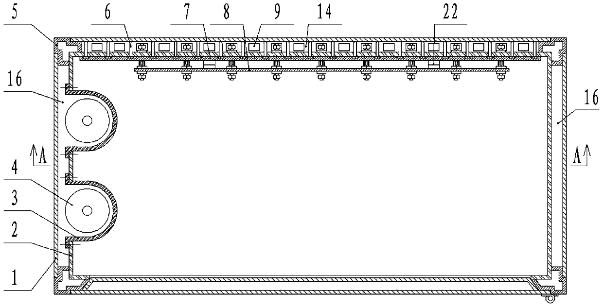
[0038] This embodiment includes a box body, a cooling fan 12 and a braking resistor 4. The cooling fan 12 and the braking resistor 4 are installed in the box body, and a fixing plate 8 for installing electrical components is arranged on the inner side of the back panel of the box body. The above are common structures in the prior art, and will not be repeated here.

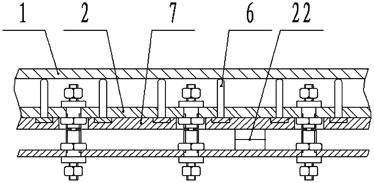
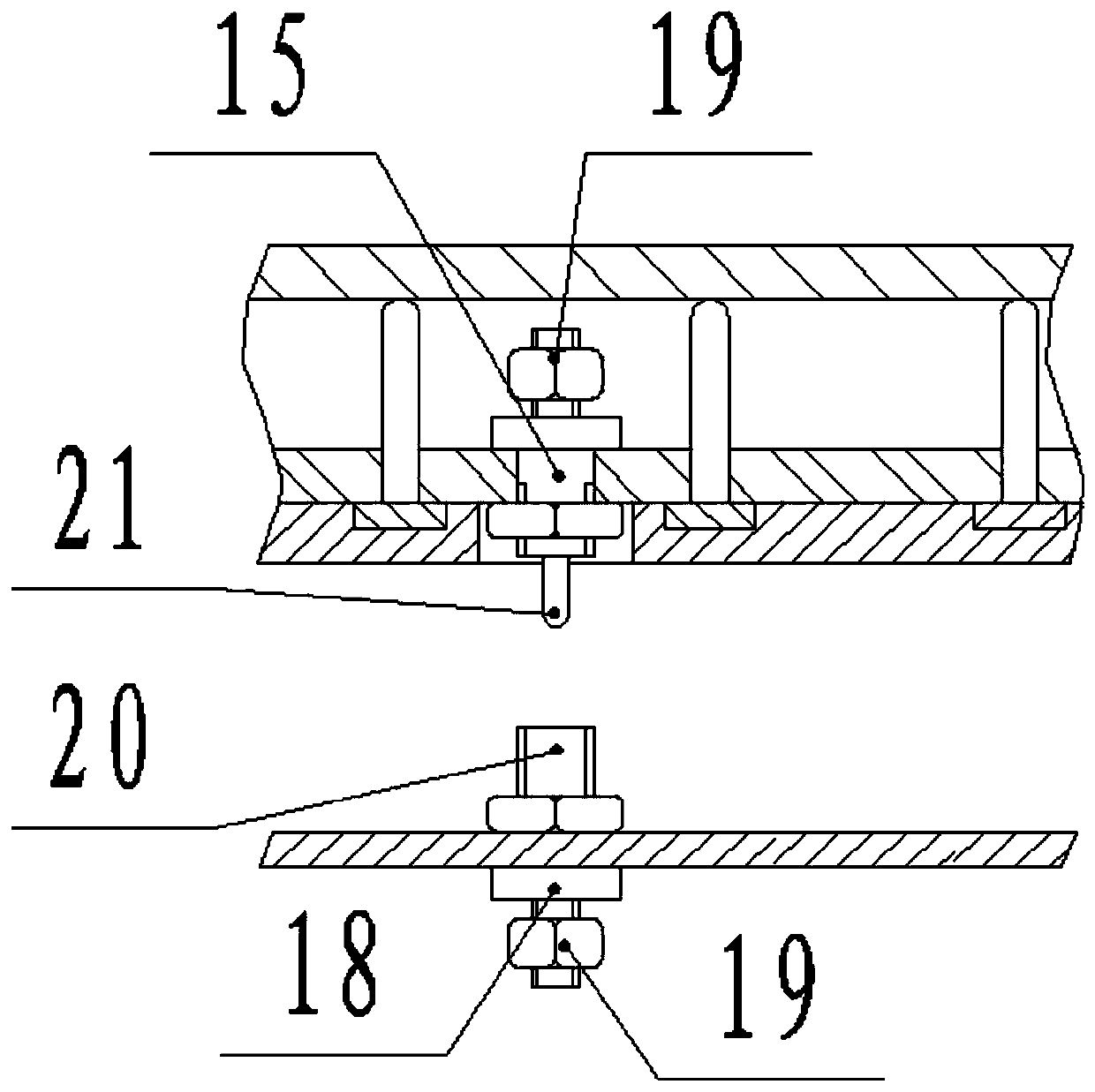
[0039] The box body is a double-layer structure, and the two-layer box body is called the inner layer box body 2 and the outer layer box body respectively. When dissipating heat, the heat in the distribution box is transferred to the interlayer between the inner box body 2 and the outer box body through heat transfer, and then dissipated to the outside of the distribution box by the cooling fan 12 .

[0040] The inner box 2 is a cubic structure surrounded by steel plates, and the outer sides of the four vertic...


PUM


Abstract

The invention belongs to the field of oilfield power equipment, and in particular relates to a distribution box with heat dissipation function, including a box body, a cooling fan and a braking resistor. The box body is a double-layer structure, and the two-layer box bodies are called inner box respectively Body and outer box, the inner box is a cubic structure surrounded by steel plates, the base and the upper cover are fixedly connected to the upper and lower ends of the installation bar, there are four cover plates, and the four cover plates are installed on the corresponding There is a gap for ventilation between the two adjacent installation bars, between the cover plate and the inner box body, that is, the air duct. In the present invention, the inner box where the electronic equipment is located is a fully enclosed structure. When dissipating heat, the heat dissipation airflow does not enter the inner box, that is, it does not flow through the electronic equipment. Therefore, the airflow in the external environment will not circulate with the air and the electronic equipment. contact, thereby completely avoiding the adverse effects of dust on electronic equipment, and effectively improving the explosion-proof performance of the distribution box.

Description

[0001] Technical field: [0002] The invention relates to the field of oil field electric equipment, in particular to a distribution box with heat dissipation function. [0003] Background technique: [0004] The distribution box is a kind of power control equipment commonly used in oil field production. In many applications in the petroleum and petrochemical industry, there are a large amount of flammable and explosive gases. In this environment, whether the explosion-proof performance of the distribution box is reliable is particularly important for safe production. The heat dissipation of the electrical components and electronic equipment inside the box needs to continuously discharge the high temperature gas in the distribution box through the cooling fan, so as to meet the heat dissipation demand. However, this method of ventilation and heat dissipation will inevitably bring inflammable and explosive gases from the outside into the distribution box, thereby greatly reduci...

Claims


Application Information

Patent Timeline
Patent Type & Authority Patents(China)
IPC IPC(8): H02B1/56H02B1/46
Inventor 徐海英
Owner DAQING CITY HUAYU PETROLEUM MASCH MFG CO LTD
Why Eureka
Try Eureka