A kind of debris flow airfoil guide groove structure

A technology for draining troughs and debris flow, which is applied to waterway systems, buildings, water supply devices, etc., can solve the problems of shortening the service life of the draining trough structure, road blockage, mud-rock fluid backflow and silting, etc., to achieve the elimination of accumulation silt problems, The effect of reducing abrasion and increasing the throwing distance of debris flow

Active Publication Date: 2020-09-04
ZAOZHUANG UNIV +2
View PDF4 Cites 0 Cited by
  • Summary
  • Abstract
  • Description
  • Claims
  • Application Information

AI Technical Summary

Problems solved by technology

A large number of engineering practices have shown that since debris flow is a high-speed mixed fluid rich in rocks, it has a strong abrasive effect on the drainage channel of concrete structures. Generally, after 5-8 times of debris flow abrasion, the steel bars will be exposed, shortening the drainage channel. service life of the structure
In addition, debris fluids are easy to accumulate at the outlet of the drainage channel, causing subsequent debris fluids to backfill and silt roads or even block rivers, resulting in secondary geological disasters

Method used


Image

  • A kind of debris flow airfoil guide groove structure
  • A kind of debris flow airfoil guide groove structure
  • A kind of debris flow airfoil guide groove structure

Examples


Embodiment Construction

[0027] Embodiments of the present invention will be described in further detail below in conjunction with the accompanying drawings.

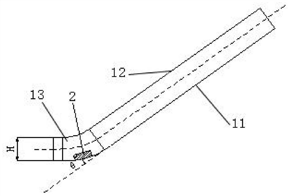
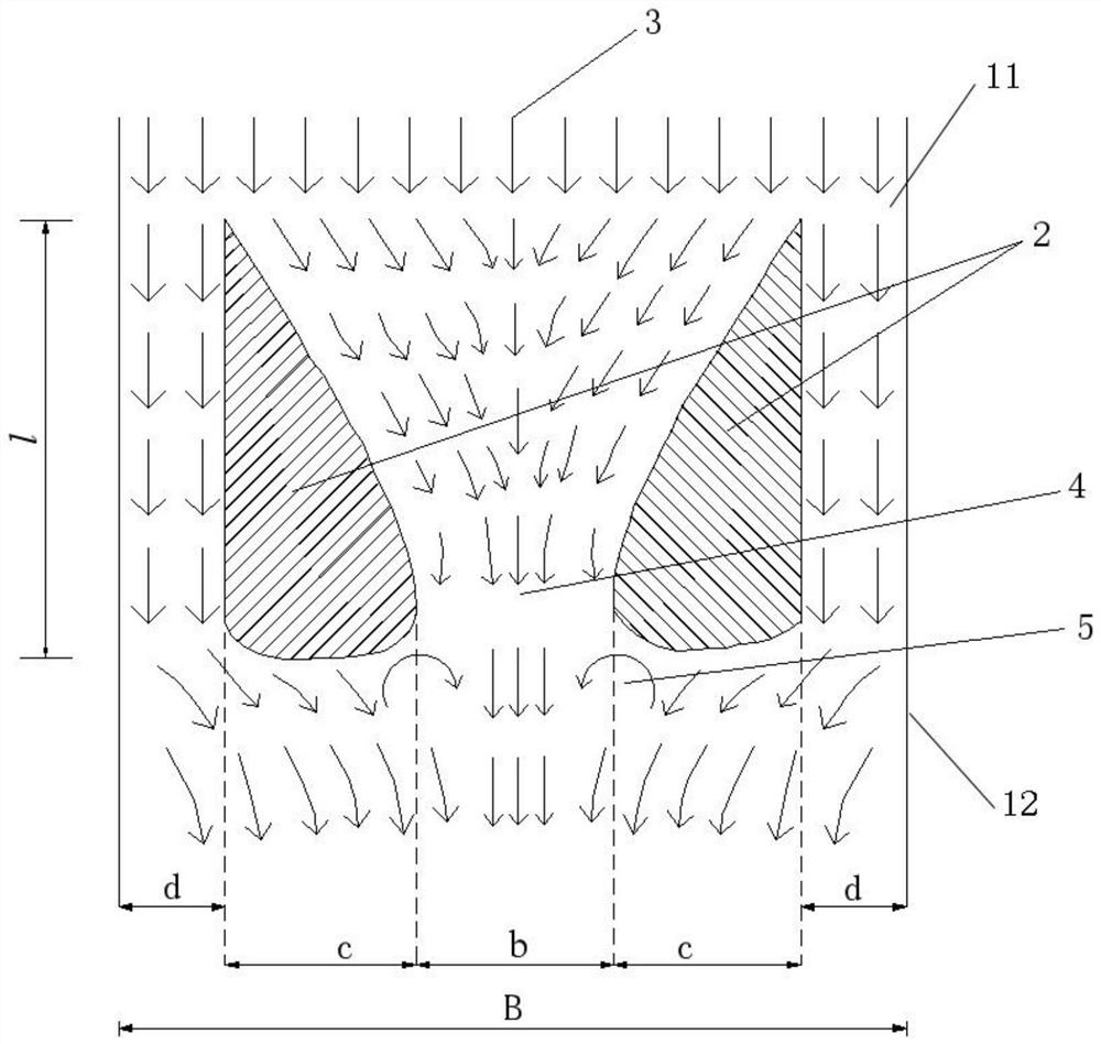
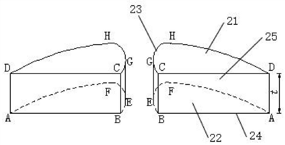
[0028] see Figure 1-Figure 3 , a debris flow airfoil guide channel structure, including the guide channel bottom surface 11 and the guide channel side walls 12 arranged on both sides of the guide channel bottom surface, the outlet section 13 of the guide channel adopts an arc-shaped structure and is reversed. The inclination angle θ is an acute angle, which is the angle between the tangent of the anti-warping point of the outlet section of the drainage channel and the straight line of the bottom surface of the inlet section of the drainage channel, so that the debris fluid is thrown horizontally or obliquely upward at the outlet section; The throwing distance solves the problem that the mud-rock fluid in the traditional linear row channel is buried at the outlet and causes the mud-rock fluid to block the river. In this embodiment, the anti-war...


PUM


Abstract

The invention discloses a debris flow wing drainage guide groove structure. The structure comprises a bottom surface of a drainage guide groove and a side wall of the drainage guide groove, an outletsection of the drainage guide groove is curved and bent upwards, and the upward bending angle theta is an acute angle, so that mudstone fluid in the outlet section is horizontally or obliquely thrown;a wing pier is oppositely disposed at the curved outlet section, the wing pier includes a top surface, a bottom surface, a head, a first side surface and a second side surface, the head of the wing pier is located at the downstream of the drainage guide groove, the first side surface is parallel to the side wall of the drainage guide groove, the oppositely disposed wing pier forms V-shaped beam flow space through the second side surface, and the debris flow forms a vortex in the head region of the wing pier. The structure can effectively reduce the abrasion effect of the debris flow on the concrete material of the drainage guide structure, and eliminate the accumulation and embedding of the mudstone fluid at the outlet portion of the drainage guide groove.

Description

technical field [0001] The invention belongs to the technical field of special equipment for road maintenance in mountainous areas, and relates to a debris flow airfoil guide groove structure. Background technique [0002] Mountain torrents and mudslide disasters occur frequently in my country. About 1.8 million kilometers of trunk roads are located in high-incidence areas of mudslides. The disasters caused by roads and mudslides are widespread and severe. In 2010 alone, the direct economic loss reached 87 billion yuan, which seriously affected the transportation capacity, transportation safety and flood relief. Rescue, as soon as possible to improve the level of flood disaster mitigation technology has become a national demand. Since the founding of New China, my country has attached great importance to the problem of debris flow disaster reduction. "Limited interception, focusing on drainage, and combining guide and drainage" is the basic principle for controlling highway d...

Claims


Application Information

Patent Timeline
Patent Type & Authority Patents(China)
IPC IPC(8): E03F3/04
Inventor 陈洪凯王圣娟
Owner ZAOZHUANG UNIV
Why Eureka
Try Eureka