
A transmission line frequency-staggered coupling vibration reduction control method

A technology of transmission lines and control methods, which is applied in the direction of mechanical vibration attenuation devices, devices for maintaining the distance between parallel conductors, etc., and can solve the problems of narrow applicable frequency band of resonance vibration reduction devices, flashover tripping between phases, and inability to play a role in vibration reduction control, etc. , to achieve an obvious effect

Active Publication Date: 2020-08-04
HUNAN UNIV OF SCI & TECH
View PDF5 Cites 0 Cited by
  • Summary
  • Abstract
  • Description
  • Claims
  • Application Information

AI Technical Summary

Problems solved by technology

[0002] Overhead transmission lines are long-span flexible structures. When excited by extreme environments such as strong winds, earthquakes, and deicing, the lines will generate large-scale low-frequency vibrations, which may easily cause phase-to-phase flashover trips, and even cause serious accidents such as line breaks and tower collapses.
The traditional damping and vibration reduction device can only be installed near the transmission tower, and it cannot effectively control the vibration of the entire line; As far as the line is concerned, its vibration reduction effect has great limitations

Method used


Image

  • A transmission line frequency-staggered coupling vibration reduction control method
  • A transmission line frequency-staggered coupling vibration reduction control method
  • A transmission line frequency-staggered coupling vibration reduction control method

Examples


Embodiment Construction

[0022] The present invention will be further described in detail below in conjunction with the accompanying drawings and embodiments.

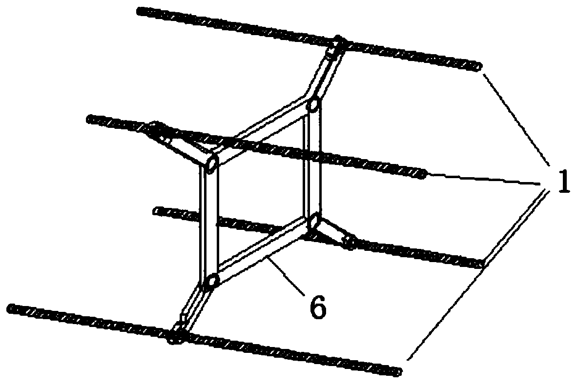
[0023] see figure 1 , is a schematic structural diagram of a three-phase four-split transmission line provided with spacer bars 6, figure 1 Among them, 2, 3, and 4 represent the first, second, and third phase four-split conductor transmission lines respectively, and 7, 8, and 9 respectively represent the interphase Spacer rods, L is the span of the transmission line, L1, L2, L3 represent the spacing of the phase-to-phase spacer rods 7, 8, 9 arranged along the line direction.

[0024] For the sake of generality, the embodiment of the present invention is based on figure 1 The shown three-phase four-split transmission line is taken as an example to illustrate, and the enlarged view of the four-split conductor part 5 with the spacer bar 6 is as follows figure 2 as shown, figure 2 In , 1 represents the four-split conductor of a certain phase...


PUM


Abstract

The invention discloses a difference frequency coupling damping control method for a transmission line, which mainly changes the original configuration of the traditional three-phase transmission linewith the same tension, the same sag, and the parallel running direction to a transmission line damping configuration with three-phase pay-off tension differences. The tension differences cause frequency differences of three-phase spring oscillators, and damping control on the whole system is realized through frequency difference match and coupling of inter-phase oscillators. In comparison with the original configuration, the sag change amplitude of the transmission line damping configuration is controlled in a moderate range, and safe operation of the line and the overall coordination and beauty of the line type are thus ensured. Through adjusting the pay-off tension of the three-phase transmission line, the large-span flexible structure vibration control problem is well solved.

Description

technical field [0001] The invention belongs to the technical field of vibration reduction of large-span flexible structures, and in particular relates to a vibration reduction control method for transmission line staggered frequency coupling based on the differential tension of pay-off wires. Background technique [0002] Overhead transmission lines are long-span flexible structures. When excited by extreme environments such as strong winds, earthquakes, and deicing, the lines will generate large low-frequency vibrations, which may easily cause phase-to-phase flashover trips, and even cause serious accidents such as line breaks and tower collapses. The traditional damping and vibration reduction device can only be installed near the transmission tower, and it cannot effectively control the vibration of the entire line; As far as the line is concerned, its vibration reduction effect has great limitations. The applicant's previous invention patent "multi-vibrator coupling tr...

Claims


Application Information

Patent Timeline
Patent Type & Authority Patents(China)
IPC IPC(8): H02G7/14H02G7/12
Inventor 谢献忠王文军彭剑梁开元吴源杰
Owner HUNAN UNIV OF SCI & TECH
Learn More