Hydraulic speed reduction device

A technology of hydraulic deceleration and speed, applied in the field of hydraulic machinery, can solve the problems of large idling loss of hydraulic reducer, failure to meet actual use needs, weakening deceleration and braking effect of hydraulic reducer, etc., to reduce idling loss, reduction in axial installation size, and reduction in installation cost

Pending Publication Date: 2019-08-02
SUZHOU TESUAN ELECTROMECHANICAL TECH CO LTD
View PDF1 Cites 0 Cited by
  • Summary
  • Abstract
  • Description
  • Claims
  • Application Information

AI Technical Summary

Problems solved by technology

When the vehicle climbs a slope and needs to generate a large braking torque, because the vehicle speed is small at this time, the braking torque generated by the hydraulic retarder is also small, so that the deceleration and braking effect of the hydraulic retarder on the vehicle is weakened, and it cannot Meet the actual use requirements; or when the vehicle is running at high speed, due to the increase in the speed of the rotor impeller, the idling loss of the hydraulic reducer will also increase accordingly

Method used


Image

  • Hydraulic speed reduction device
  • Hydraulic speed reduction device
  • Hydraulic speed reduction device

Examples


Embodiment 1

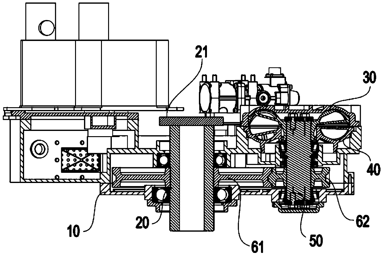
[0033] combine image 3 and Figure 4 As shown, the speed regulating mechanism 60 includes a first speed change gear 61 and a second speed change gear 62, wherein the first rotating shaft 20 is pivotally connected to the first speed change gear 61, the second rotating shaft 50 is pivotally connected to the second speed change gear 62, and the first speed change gear 61 is meshed with the second transmission gear 62 . During specific implementation, the first rotating shaft 20 drives the first transmission gear 61 to rotate, and the first transmission gear 61 further drives the second transmission gear 62 meshed with it to rotate; the second transmission gear 62 drives the second rotation shaft 50 to rotate, and then drives the rotor The impeller 30 rotates so that the rotational speed of the rotor impeller 30 is changed under the action of the first speed change gear 61 and the second speed change gear 62 , thereby changing the braking torque of the hydraulic speed reduction ...

Embodiment 2

[0036] Such as Figure 5 As shown, the speed regulating mechanism 60 includes a first speed change gear 61, a second speed change gear 62, a third speed change gear 63, a fourth speed change gear 64 and a third rotating shaft 65, wherein the third rotating shaft 65 is pivotally connected to the third speed changing gear 63 and the fourth speed change gear 64, the first shaft 20 is pivotally connected to the first speed change gear 61, and the first speed change gear 61 is meshed with the third speed change gear 63, the second shaft 50 is pivotally connected to the second speed change gear 62, and the second The transmission gear 62 is engaged with the fourth transmission gear 64 .

[0037] During specific implementation, the first rotating shaft 20 drives the first transmission gear 61 to rotate, and the first transmission gear 61 further drives the third transmission gear 63 meshed with it to rotate; the second transmission gear 62 drives the third rotation shaft 65 to rotate, ...

Embodiment 3

[0040] Such as Figure 6 As shown, the speed regulating mechanism 60 includes a first speed change gear 61, a second speed change gear 62, a third speed change gear 63, a fourth speed change gear 64 and a clutch 66, wherein the first rotating shaft 20 is connected to the first speed change gear 61 and the second speed change gear 61. Three-speed gear 63, the second rotating shaft 50 is connected to the second speed-change gear 62 and the fourth speed-change gear 64, and the first speed-change gear 61 is meshed with the second speed-change gear 62, and the third speed-change gear 63 and the fourth speed-change gear 64 Further, the clutch 66 is installed on the second rotating shaft 50 and is located between the second transmission gear 62 and the fourth transmission gear 64, which can be connected with any of the second transmission gear 62 and the fourth transmission gear 64. One is combined, and it can also be separated from both the second speed change gear 62 and the fourth...


PUM


Abstract

The invention discloses a hydraulic speed reduction device. The hydraulic speed reduction device is installed and attached to a vehicle speed changing box and is connected with the vehicle speed changing box in series. The hydraulic speed reduction device comprises a shell and a first rotation shaft and further comprises a rotor impeller, a stator impeller, a second rotation shaft and a speed adjusting mechanism which are integrated in the shell. A work cavity is formed between the rotor impeller and the stator impeller. The second rotation shaft is connected with the rotor impeller. The firstrotation shaft stretches into the shell and is connected with the second rotation shaft through the speed adjusting mechanism. One end of the first rotation shaft is connected with an output shaft ofthe vehicle speed changing box, and the opposite end is connected with a drive axle. The speed adjusting mechanism is integrated in the shell of the hydraulic speed reduction device, the hydraulic speed reduction device has the function of speed adjusting, meanwhile, the installing manner of the hydraulic speed reduction device is changed, the hydraulic speed reduction device is installed and attached to the vehicle speed changing box and is connected with the vehicle speed changing box in series, and the axial installing size is effectively reduced.

Description

technical field [0001] The invention relates to the technical field of hydraulic machinery, in particular to a hydraulic deceleration device installed between a vehicle gearbox and a vehicle drive axle. Background technique [0002] For vehicles with high speed and heavy loads, and vehicles requiring short braking distance and quick response, traditional mechanical friction brakes alone cannot meet people's requirements for vehicle safety, and hydraulic retarders can safely and reliably assist vehicle braking. To make the vehicle meet the safety requirements, therefore, it is widely used in vehicles. [0003] The hydraulic reducer is a device that converts mechanical energy into liquid heat energy and has low wear and tear. It is composed of a rotor impeller, a stator impeller, and a rapid liquid filling and discharging mechanism. A working chamber is formed between the rotor impeller and the stator impeller. When working, the rotor impeller is driven by the transmission sy...

Claims


Application Information

Patent Timeline
Patent Type & Authority Applications(China)
IPC IPC(8): F16D57/02F16D65/78F16H1/04F16H1/22F16H3/089
CPCF16D57/007F16D57/02F16D65/78F16H1/04F16H1/22F16H3/006F16H3/089F16H2200/0034F16H2200/2033
Inventor 付凤吉于海刘永刚宋立涛乔亚松
Owner SUZHOU TESUAN ELECTROMECHANICAL TECH CO LTD
Why Eureka
Try Eureka