A Switched Reluctance Generator Converter System

A converter system and switched reluctance technology, which is applied in the direction of controlling the generator through the change of the magnetic field, controlling the generator, and controlling the system, can solve the problems of large fluctuations in the output terminal, increased voltage, and low reliability, and achieve Improved boosting effect, low switching frequency, and improved reliability

Active Publication Date: 2021-02-12
浙江知多多网络科技有限公司
View PDF10 Cites 0 Cited by
  • Summary
  • Abstract
  • Description
  • Claims
  • Application Information

AI Technical Summary

Problems solved by technology

[0003] The switched reluctance generator works like a DC power supply, but in practice, after it outputs DC power, it often needs a special booster device to increase the voltage, and then merges it into the DC grid or connects the load, resulting in a complex structure of the entire converter system , high loss, low reliability
[0004] The excitation methods of switched reluctance generators generally include separate excitation and self-excitation. The excitation of the external excitation mode is stable and does not affect the output terminal, but the maintenance cost is high and requires a separate excitation power supply such as a battery. The self-excitation mode does not require a separate power supply. The separately excited type has the disadvantages of often replacing the battery, etc., but it will generally cause large fluctuations at the output end, and at the same time, the input excitation power is unstable and the power quality is low; at present, there are also some excitation methods, which are powered by the battery and absorb the advantages of the separately excited type. , when necessary, use the electric energy at the output end to charge the battery, thus also absorbing the advantages of the self-excited type
[0005] In the field of wind power, the traditional doubly-fed asynchronous wind power generator system can provide electric energy to the output terminal at the same time in the stator and rotor windings when necessary, especially when the wind power grid is connected to the low voltage and other faults, it plays a very important role. In the field of application of resistance generators, the double-fed function cannot be realized in the traditional mode. In addition, considering the special circumstances of the load side, if the separately excited battery of the switched reluctance generator converter system has excitation and can also provide electric energy to the output terminal, It is bound to improve the adaptability of the entire power generation system

Method used


Image

  • A Switched Reluctance Generator Converter System

Examples


Embodiment Construction

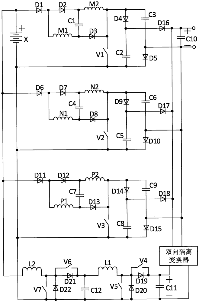
[0020] A switched reluctance generator converter system of this embodiment, as attached figure 1 As shown, it consists of battery X, first diode D1, second diode D2, third diode D3, fourth diode D4, fifth diode D5, sixth diode D6, Seventh diode D7, eighth diode D8, ninth diode D9, tenth diode D10, eleventh diode D11, twelfth diode D12, thirteenth diode D13, fourteenth diode D14, fifteenth diode D15, sixteenth diode D16, seventeenth diode D17, eighteenth diode D18, nineteenth diode D19, Twenty-first diode D20, twenty-first diode D21, twenty-second diode D22, one winding M1 of the first phase winding, two windings M2 of the first phase winding, one winding of the second phase Winding N1, two windings N2 of the second phase winding, one winding P1 of the third phase winding, two windings P2 of the third phase winding, the first capacitor C1, the second capacitor C2, the third capacitor C3, the fourth capacitor C4, The fifth capacitor C5, the sixth capacitor C6, the seventh capa...


PUM


Abstract

A switched reluctance generator converter system, which consists of a battery, 22 diodes, three-phase windings, seven switch tubes, twelve capacitors, two inductors, and a bidirectional isolation converter. Under the structure, through the automatic parallel excitation of two branch windings of each phase winding, the excitation capability is enhanced, and the two branch windings of each phase winding are automatically connected in series to generate electricity and combined with the battery and related capacitors to achieve a full series high boost output. In the process, only one Realization of switching tubes solves the problem of directly outputting very high voltage under the minimum switching tubes, the battery can be charged automatically, and the same set of converter circuits can also realize reverse energy feedback, which improves the level of intelligence and adapts to the output of the converter system When the end load side needs more power, the system can still meet the requirements. The maximum withstand voltage value of each switching tube in the whole system is low, and the switching loss is low. It is suitable for switching reluctance under various power inputs and grid-connected or direct loads. Generator converter system application.

Description

technical field [0001] The invention relates to the field of switched reluctance motor systems, in particular to a switched reluctance generator converter system with direct high boost ratio, automatic battery charging and energy feeding. Background technique [0002] Because of its simple and firm structure, no winding on the rotor, convenient heat dissipation, high reliability, and strong fault tolerance, the switched reluctance motor has a wide range of application prospects. [0003] The switched reluctance generator works like a DC power supply, but in practice, after it outputs DC power, it often needs a special booster device to increase the voltage, and then merges it into the DC grid or connects the load, resulting in a complex structure of the entire converter system , high loss and low reliability. [0004] The excitation methods of switched reluctance generators generally include separate excitation and self-excitation. The excitation of the external excitation ...

Claims


Application Information

Patent Timeline
Patent Type & Authority Patents(China)
IPC IPC(8): H02P9/30H02P9/38H02P101/15
CPCH02P9/305H02P9/38H02P2101/15
Inventor 孙冠群蔡慧郭倩
Owner 浙江知多多网络科技有限公司
Why Eureka
Try Eureka