Method for generating load signal using boomerang technique

A technology of loading signals and signals, applied in the direction of telephone communication, automatic switching office, instruments, etc., can solve the problems of rapid increase, bottleneck, entering the initialization state, etc., to achieve the effect of improving reliability

Inactive Publication Date: 2003-03-05
SAMSUNG ELECTRONICS CO LTD
View PDF2 Cites 0 Cited by
  • Summary
  • Abstract
  • Description
  • Claims
  • Application Information

AI Technical Summary

Problems solved by technology

In this way, the software of the processor may accidentally enter the initialization state
[0005] Second, although the load is limited to a limit to avoid signal queue overflow, the load on the test processor can increase rapidly creating a bottleneck in extreme cases
[0006] Furthermore, the events required by other processors or the timing signals generated by ...

Method used


Image

  • Method for generating load signal using boomerang technique
  • Method for generating load signal using boomerang technique
  • Method for generating load signal using boomerang technique

Examples


specific Embodiment approach

[0013] DETAILED DESCRIPTION OF THE PREFERRED EMBODIMENTS The preferred embodiments of the present invention will be described in detail below with reference to the accompanying drawings.

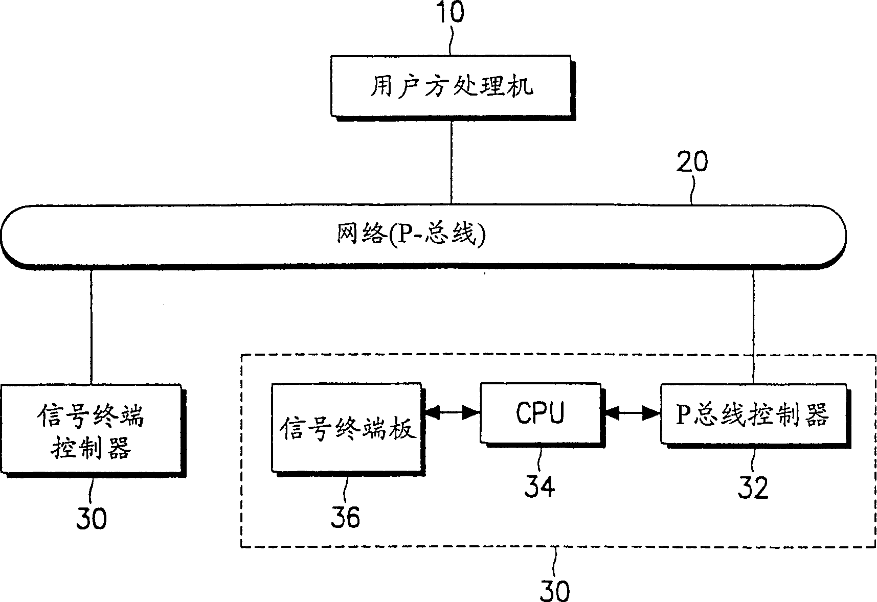
[0014] see figure 1 . A general No. 7 common channel signaling system includes a network (or P bus) 20 , a user-side processor 10 and a pair of signal terminal controllers 30 . Each signal terminal processor 30 is composed of a P bus controller 32 , a CPU (central processing unit) 34 with a timer, and a signal terminal board 36 . Each signal terminal controller 30 is on the same backplane so as to share the load under normal conditions, and when one of the signal terminal controllers 30 fails to control the signal chain of the faulty part. The P bus controller 32 makes the P bus work with the signal terminal controller 30 under the control of the CPU34. The CPU 34 controls the overall operation of the signal terminal controller 30 . The user side processor 10 is equipped with the pseudo ...


PUM


Abstract

A pseudosimulation of signals,invention refers to measurement of characteristics of electronic commutation system and can be used for stable generation of load signals in response to boomerang signal. All load signals are generated in the course of each unit time interval is less than limit number of load signals which tested processor can process. But if number of load signals that should be generated in the course of each mentioned unit time interval would exceed limit number than load signals will be generated in amount equal to limit number and boomerang signal will be generated. The rest of load signals will be generated then after reception of mentioned boomerang signal.

Description

technical field [0001] The present invention relates to a pseudo-load box for measuring the performance of an electronic switching system, and more specifically, to a method for stably generating a load signal for measuring the performance of an electronic switching system within a unit time. Background technique [0002] A pseudo-loadbox (or emulation program) is a software program, usually used with electronic switching systems. This pseudo-load box generates a series of pseudo-signals within a certain period of time to determine the limitation of system capabilities and analyze the bottleneck phenomenon of the switching system. Based on the measurement and analysis results, operators can improve system performance and control system overload conditions. [0003] Usually, the pseudo-load box periodically generates a timing signal and a certain number of load signals per unit time. For example, to verify that a processor in a switching system can handle 100 events per sec...

Claims


Application Information

Patent Timeline
IPC IPC(8): G05B17/00H04M3/26H04Q1/20
CPCH04M3/26H04M3/362H04M3/365
Inventor 河甲秀
Owner SAMSUNG ELECTRONICS CO LTD
Why Eureka
Try Eureka