
A kind of fast measuring device and measuring method of deflection of long part
The technology of a measuring device and measuring method is applied in the field of rail vehicles to achieve the effects of overcoming measurement errors, reducing measurement errors and ensuring accuracy
- Summary
- Abstract
- Description
- Claims
- Application Information
AI Technical Summary
Problems solved by technology
Method used
Image

Examples
Embodiment Construction
[0030] The present invention will be further described below in conjunction with accompanying drawing:
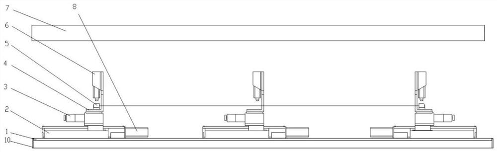
[0031] Such as figure 1 As shown in , it is a schematic diagram of the structure of the rapid measurement device for long component deflection.
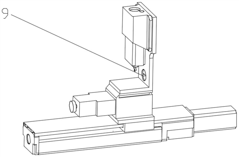
[0032] The device for quickly measuring the deflection of a large part of the present invention comprises a frame 1, on which three ball screw modules 2 are arranged along the same straight line, and one end of the ball screw module 2 is provided with a servo motor 8, the ball screw module A sliding table 3 is fixedly installed on the mounting plate above the group 2, an L-shaped mounting plate 4 is arranged on the sliding table 3, and a laser displacement sensor 6 is arranged on the upper end of the L-shaped mounting plate 4; The through-beam laser sensor 6 is relatively arranged respectively; the frame is provided with a controller, and the controller is electrically connected with the laser displacement sensor 6, the servo mot...
PUM
 Abstract
Description
Claims
Application Information