Full-automatic welding machine for automotive frame

A fully automatic technology for automobile girders, applied to vehicle parts, welding accessories, welding rod characteristics, etc., can solve the problems of inconsistent welding thickness of arc surface structures on both sides, inability to realize automatic flipping, and inability to realize automatic welding, etc., so as to improve welding quality , reduce the burden on workers and improve welding efficiency

Pending Publication Date: 2019-12-03
山东越浩自动化设备有限公司
View PDF0 Cites 2 Cited by
  • Summary
  • Abstract
  • Description
  • Claims
  • Application Information

AI Technical Summary

Problems solved by technology

At present, when the girder is being welded, it cannot be turned over automatically. It needs to rely on the manual control of the crane to turn over, and the work efficiency is low.
In addition, the arc surface structure on both sides of the beam workpiece is inconsistent, and the existing welding machine cannot realize automatic welding. Manually operated welding machine welding has the defect that the welding thickness of the arc surface structure on both sides is inconsistent, which makes the welding quality poor

Method used


Image

  • Full-automatic welding machine for automotive frame
  • Full-automatic welding machine for automotive frame
  • Full-automatic welding machine for automotive frame

Examples


Embodiment 1

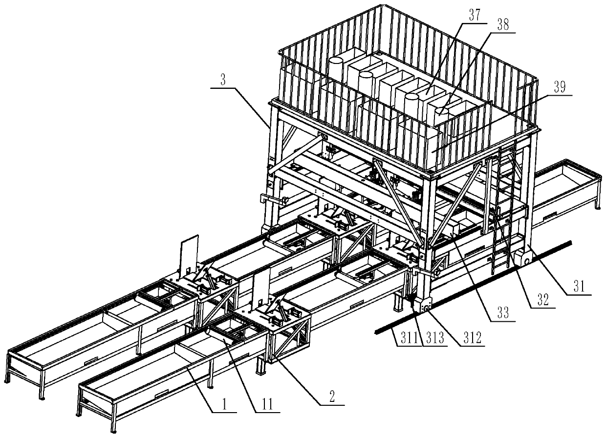
[0033] Embodiment one: if figure 1 As shown, the described automatic frame welding machine for automobiles includes a tooling frame 1, on which a roller 11 is arranged, and the roller 11 is convenient for adjusting the position of the frame workpiece 4; 1 An automatic welding device 3 that moves back and forth in the longitudinal direction. The automatic welding device 3 is provided with a fixed beam 32 and a movable beam 33 that can move back and forth along the length direction of the tooling frame 1. The fixed beam 32 and the movable beam 33 are respectively provided with more than one set of An automatic welding torch that can move left and right along the length direction of the movable beam 33.

[0034] Such as Figure 7 As shown, in the present embodiment, two groups of automatic welding guns are respectively arranged on the fixed beam 32 and the movable beam 33, which can realize simultaneous welding operations of two beam workpieces 4, and the automatic welding guns ...

Embodiment 2

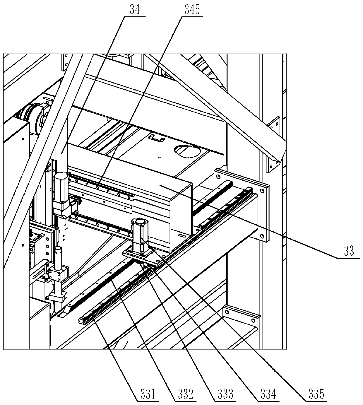
[0047] Embodiment 2: The supporting beam is provided with a second track 331, the bottom of the movable beam 33 is provided with a slide plate, the main body walking frame 31 is fixedly connected with an electric telescopic rod, and the protruding end of the electric telescopic rod is connected with the bottom of the movable beam 33; Others are the same as in Embodiment 1. The electric telescopic rod drives the movable beam 33 to move back and forth.

Embodiment 3

[0048] Embodiment three: the first track 311 is provided under the main body walking frame 31, the first track 311 is provided with a rack one, the bottom of the main body walking frame 31 is provided with a first motor 313, and the output end of the first motor 313 is provided with Gear one, gear one meshes with rack one; others are the same as embodiment one. The first motor 313 drives the main body walking frame 31 to move forward and backward through the cooperating gear one and rack one.

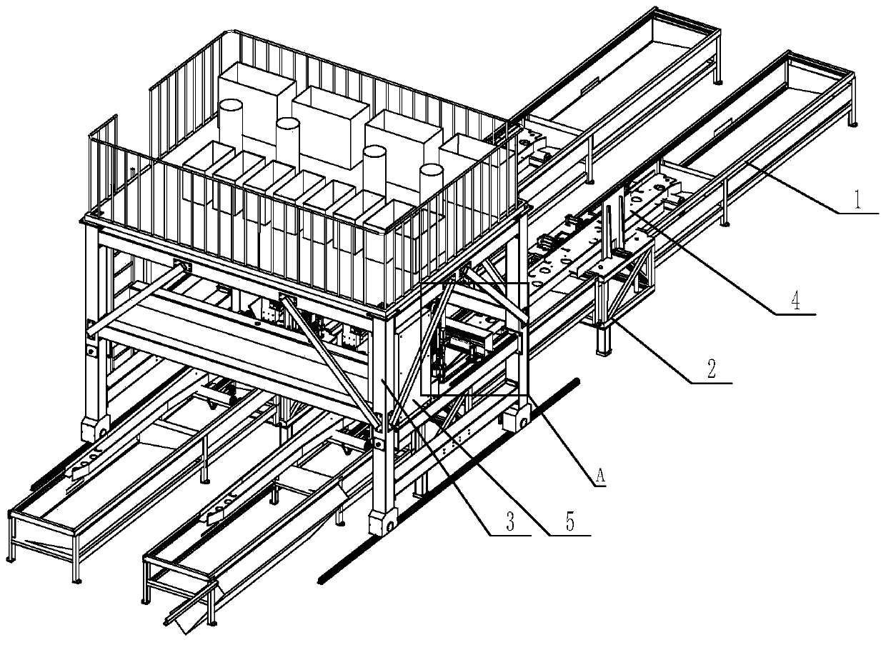
[0049] Such as figure 2 As shown, two beam workpieces 4 are respectively placed on the tooling frame 1, and the beam workpieces 4 are placed between the pushing cylinder 204 and the turnover plate 206 of the beam turning mechanism 2, and the position of the beam workpiece 4 is adjusted by the roller 11, so that Two beam workpieces 4 are on a horizontal line.

[0050] The present invention is also provided with distribution box, operation panel and PLC control module when making on ma...


PUM


Abstract

The invention discloses a full-automatic welding machine for an automobile frame, and belongs to the field of automobile frame welding. The full-automatic welding machine mainly comprises a tool frame; an automatic welding device capable of moving front and back in the length direction of the tool frame is arranged above the tool frame, a movable beam capable of moving front and back in the lengthdirection of the tool frame is arranged on the automatic welding device, and one or more sets of automatic welding guns capable of moving left and right in the length direction of the movable beam are arranged on the movable beam. According to the welding machine, multiple weld joints can be welded at the same time, two or more frames can be welded at the same time, the frames can be automatically turned over, and the working efficiency is greatly improved. The welding machine is mainly used for welding the automotive frame.

Description

technical field [0001] The invention belongs to the field of automobile beam welding, and in particular relates to a fully automatic welding machine for automobile beams. Background technique [0002] The beam workpiece is the main component of the trailer frame. It is set in the middle of the frame. It is generally divided into a left longitudinal beam and a right longitudinal beam. The cross section is usually an I-shaped structure. In the trailer production process, the girder needs to be welded, and after one side of the girder is welded, the girder needs to be turned over to weld the other side. At present, when the girder is being welded, it cannot be turned over automatically, and it needs to be turned over manually by a crane, and the work efficiency is low. Moreover, the arc surface structure on both sides of the beam workpiece is inconsistent, and the existing welding machine cannot realize automatic welding. Manually operated welding machine welding has the defec...

Claims


Application Information

Patent Timeline
Patent Type & Authority Applications(China)
IPC IPC(8): B23K37/00B23K37/047B23K37/02B23K9/00B23K9/26B23K9/32
CPCB23K9/00B23K9/26B23K9/32B23K37/00B23K37/0211B23K37/047B23K2101/006
Inventor 巩用亭袁钥于汝臣
Owner 山东越浩自动化设备有限公司
Why Eureka
Try Eureka