Laminated glass and production method for laminated glass

A technology of laminated glass and glass plate, applied in the direction of glass/slag layered products, chemical instruments and methods, layered products, etc., can solve problems such as liquid crystal leakage, worry about aging of seals, and gaps in laminated glass, so as to prevent aging Effect

Pending Publication Date: 2020-04-21
DAI NIPPON PRINTING CO LTD
View PDF10 Cites 2 Cited by
  • Summary
  • Abstract
  • Description
  • Claims
  • Application Information

AI Technical Summary

Problems solved by technology

In addition, there may be voids in a part of the laminated glass
When such liquid crystal deposits or voids exist, they can only be discarded as defective products, so improvement is expected
[0007] In addition, the liquid crystal film is constituted by sealing the liquid crystal layer with a seal, but depending on the usage environment, there may be concerns about the deterioration of the seal due to sunlight irradiating the seal.
If the sealing member is deteriorated, the liquid crystal in the liquid crystal layer may leak out, so countermeasures are expected

Method used


Image

  • Laminated glass and production method for laminated glass
  • Laminated glass and production method for laminated glass
  • Laminated glass and production method for laminated glass

Examples


no. 1 approach

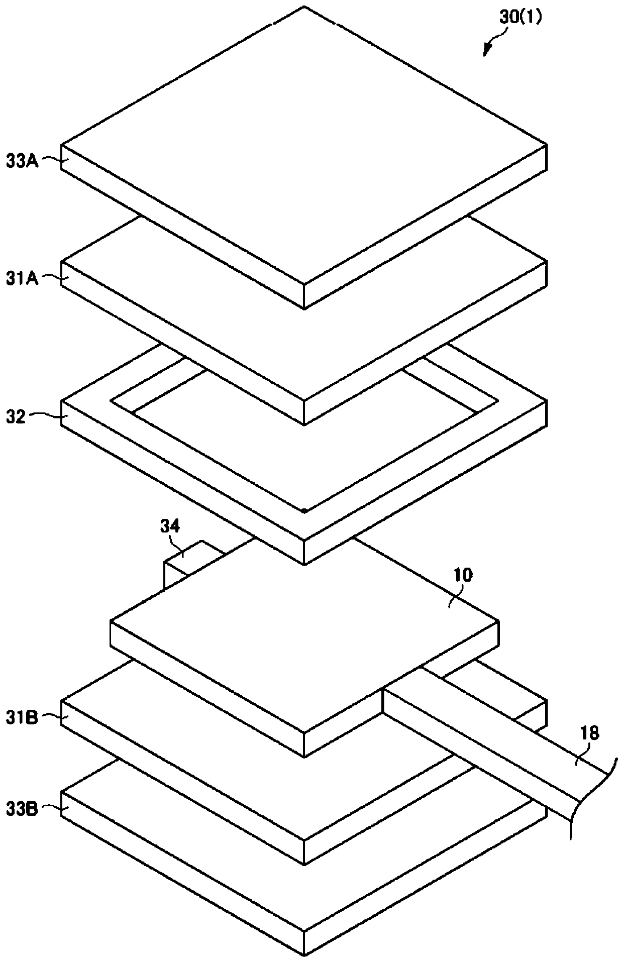
[0059] figure 1 It is an exploded perspective view showing the structure of the laminated body 30 of this embodiment.

[0060] It should be noted that, including figure 1 In addition, each figure shown below is a schematic figure, and the size and shape of each part are exaggerated suitably for easy understanding.

[0061] In addition, in the following description, specific numerical values, shapes, materials, and the like are shown and described, but they can be appropriately changed.

[0062] In this specification, terms that limit shapes or geometric conditions, such as parallel or orthogonal, etc., in addition to expressing strict meanings, realize the same optical function, and have errors that are considered to be parallel or orthogonal. Status is also included.

[0063] In this specification, words such as plate, sheet, and film are used. As a general method of use, these are used in the order of plate, sheet, and film in the order of thickness from thick to thin. i...

no. 2 approach

[0192] Figure 20 It is a cross-sectional view showing a use state where the laminated glass 1A of the second embodiment is attached to a frame body F. FIG. In this 2nd Embodiment and the 3rd Embodiment mentioned later, the structure which fixed and attached laminated glass 1A (1B) to the frame-shaped frame body (window frame) F is demonstrated.

[0193] The laminated glass 1A of the second embodiment has further added components necessary for actual use, but the basic structure is the same as that of the laminated glass 1 of the first embodiment. Therefore, parts that achieve the same functions as those in the above-mentioned first embodiment are assigned the same reference numerals, and redundant descriptions are appropriately omitted.

[0194] Figure 20 The cross section of is cut and shown near the end of the laminated glass 1A in a state where the laminated glass 1A is attached to the frame body F. The laminated glass 1A is constructed with Figure 20 The layer struc...

no. 3 approach

[0209] Figure 21 It is a cross-sectional view showing a use state in which the laminated glass 1B of the third embodiment is attached to a frame body F. FIG.

[0210] The laminated glass 1B of the third embodiment differs from the second embodiment in that it includes light shielding portions 70A and 70B, and its basic structure is the same as that of the laminated glass 1A of the second embodiment. Therefore, parts that realize the same functions as those in the above-mentioned second embodiment are assigned the same reference numerals, and redundant descriptions are appropriately omitted.

[0211] In the third embodiment, two (two layers) of light shielding portions of 70A of light shielding portions and light shielding portion 70B are included.

[0212] 70 A of light shielding parts of 3rd Embodiment are comprised similarly to 70 A of light shielding parts of 2nd Embodiment.

[0213] The light shielding portion 70B of the third embodiment is arranged at a position betwee...


PUM


Abstract

Provided are a laminated glass which has a reduced occurrence of voids and accumulation of liquid crystal, and a production method for the laminated glass. Also provided is a laminated glass which canprevent deterioration of a sealing material. This laminated glass 1 comprises a first glass plate 33A, a first intermediate film 31A, a liquid crystal film 10, a second intermediate film 31B, and a second glass plate, which are layered and disposed in this order, wherein the first glass plate 33A and the second glass plate 33B have a larger outer shape than that of the liquid crystal film 10, anda spacer 32 is provided in at least a portion of a region which is interposed between the first glass plate 33A and the second glass plate 33B and in which the liquid crystal film 10 is not disposed.

Description

technical field [0001] The invention relates to laminated glass and a method for manufacturing the laminated glass. Background technique [0002] Conventionally, a dimming member has been proposed that can be used, for example, in an electric blind that is attached to a window to control transmission of external light (Patent Document 1, Patent Document 2). As one of such dimming components, there is a component using liquid crystal. [0003] A liquid crystal film as a dimming component using liquid crystals is made by sandwiching a liquid crystal material between transparent plates including transparent electrodes to make a liquid crystal cell, and the liquid crystal cell is made by sandwiching the liquid crystal cell with linear polarizers. The liquid crystal film changes the orientation of the liquid crystal by changing the electric field applied between the transparent electrodes, and controls the amount of transmission of external light. [0004] Furthermore, it has b...

Claims


Application Information

Patent Timeline
Patent Type & Authority Applications(China)
IPC IPC(8): C03C27/12B32B3/02B32B17/10
CPCB32B17/10761B32B17/10788B32B17/10293B32B17/10302B32B17/10036B32B17/10504B32B17/10348B32B7/023B32B3/18B32B17/10779B32B2305/55G02F1/133388B32B17/10005B32B3/085B32B17/10467G02F1/133512G02F1/13394
Inventor 石井宪雄三浦启介萩原裕介
Owner DAI NIPPON PRINTING CO LTD
Why Eureka
Try Eureka