A fast filament feeding device for fdm type 3d printing filament

A 3D printing and fast technology, applied in the field of 3D printing, can solve the problems of unable to move at a uniform speed and low universality, so as to improve the efficiency of spacing adjustment, avoid jamming or bending, and improve universality

Active Publication Date: 2020-08-04
合肥名龙电子科技有限公司
View PDF3 Cites 0 Cited by
  • Summary
  • Abstract
  • Description
  • Claims
  • Application Information

AI Technical Summary

Problems solved by technology

[0004] The purpose of the present invention is to provide a fast wire feeding device for FDM type 3D printing filament to solve the problem of low universality caused by the fixed gear spacing in the prior art and the current problems caused by the change of wire diameter during the wire feeding process. Unable to move at a uniform speed and the problem of thread jamming, to achieve the purpose of more reliable and flexible threading

Method used


Image

  • A fast filament feeding device for fdm type 3d printing filament
  • A fast filament feeding device for fdm type 3d printing filament
  • A fast filament feeding device for fdm type 3d printing filament

Examples


Embodiment 1

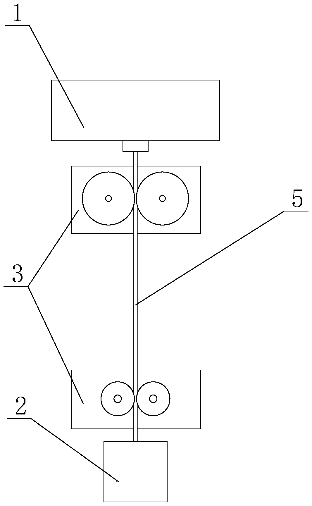
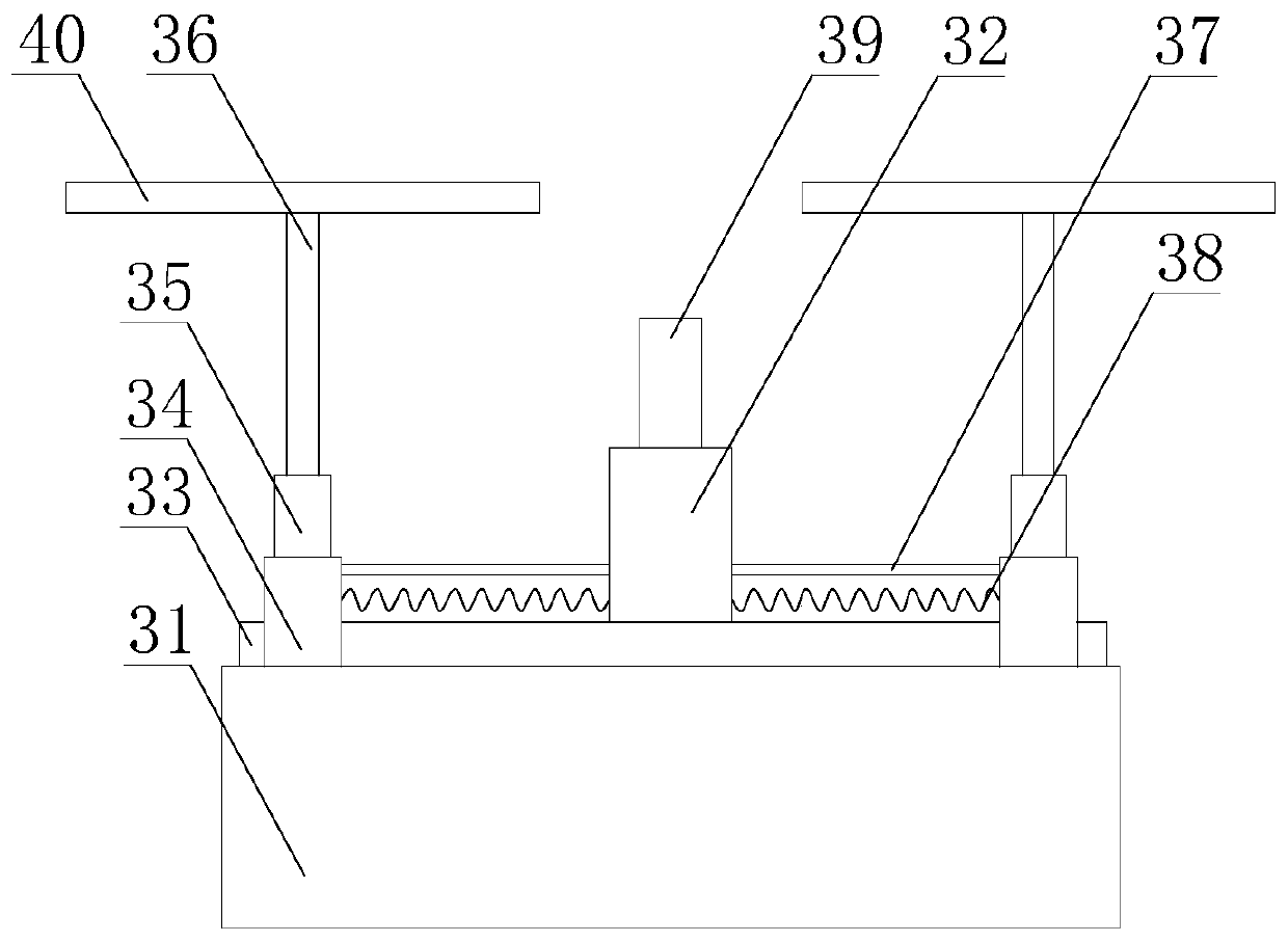
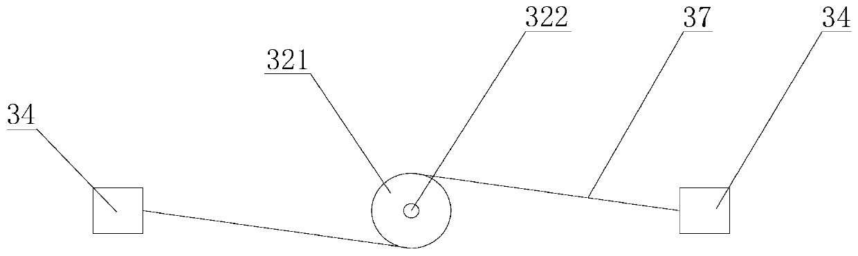
[0038] like Figure 1 to Figure 4 A fast filament feeding device for FDM type 3D printing is shown, which includes a first feeding mechanism close to the feeding tank 1 and a second feeding mechanism close to the nozzle 2. The structures of the first and second feeding mechanisms are basically the same, both It includes a base 31 located between the feeding tank 1 and the spray head 2, the base 31 is provided with a rail 33, and the rail 33 is slidably provided with two sliders 34, and the slider 34 is provided with a first driving device 35, the output end of the first driving device 35 is connected to the wire feeding reel 40 through the first rotating shaft 36, the first driving device 35 is used to drive the wire feeding reel 40 to rotate, the distance between the two wire feeding reels (40) Matches the diameter of the wire 5; the base 31 is provided with a distance adjustment mechanism 32, and the distance adjustment mechanism 32 is used to adjust the distance between the...

Embodiment 2

[0044] On the basis of Example 1, such as Figure 5 As shown, along the circumferential direction of the wire feeding reel 40, an annular groove 41 is provided on the side of the wire feeding reel 40; a wire feeding ring 42 is arranged in the annular groove 41, and the wire feeding ring 42 is made of a flexible material to make.

[0045] In some embodiments, the wire feeding ring 42 is made of nitrile rubber or silicon rubber.

[0046] The above setting not only prevents the wire from moving in the vertical direction during the transmission process, but also increases the contact area between the wire and the wire feeding ring in the annular groove, and the higher friction coefficient of the rubber improves the feeding speed. The friction between the wire loop and the wire significantly improves the transmission efficiency.


PUM


Abstract

The invention discloses a rapid filament feeding device used for FDM type 3D printing material filaments. The rapid filament feeding device comprises at least one feeding mechanism. Each feeding mechanism comprises a base located between a feeding tank and a spray nozzle. A rail is arranged on each base. Two slide blocks are arranged on each rail in a sliding manner. A first drive device is arranged on each slide block. The output end of each first drive device is connected with a wire feeding disc through a first rotating shaft. The first drive devices are used for driving the wire feeding discs to rotate. The gap between every corresponding wire feeding discs is matched with the diameter of wire rods. After the diameter of the to-be-conveyed wire rods is confirmed, the relative positions, on the rails, of the slide blocks are adjusted, the gap between every two corresponding wire feeding discs is then changed, the gap is made to be matched with the diameter of the to-be-conveyed wirerods, and the situation that after the diameter of the wire rods is changed, the wire rods get stuck or cannot be conveyed is avoided; and meanwhile, universality of the filament feeding device is improved, and the rapid filament feeding device can meet wire rod diameter requirements under different working conditions.

Description

technical field [0001] The invention relates to the technical field of 3D printing, in particular to a fast filament feeding device for FDM type 3D printing filament. Background technique [0002] Since the advent of 3D printing technology, it has made continuous progress and development in its design and innovation. At this stage, the types of 3D printing mainly include fused deposition (FDM) type, layered solid manufacturing type, and laser sintering type. Among them, the FDM printer is currently the most widely used type of 3D printer in the market. Its principle is mainly to feed the solid molding material into the nozzle of the 3D printer through the feeding device, and the nozzle will heat the solid molding material into a semi-molten state and then extrude it. , and print layer by layer according to the preset trajectory, and finally form a solid body. [0003] The existing feeding device usually uses two symmetrically arranged gears to push the wire forward or back...

Claims


Application Information

Patent Timeline
Patent Type & Authority Patents(China)
IPC IPC(8): B29C64/321B29C64/118B29C64/393B29C64/386B33Y40/00B33Y50/00B33Y50/02
CPCB29C64/118B29C64/321B29C64/386B29C64/393B33Y40/00B33Y50/00B33Y50/02
Inventor 代艳霞黄河张德红门延会廖璘志毛羽胡蓉
Owner 合肥名龙电子科技有限公司
Why Eureka
Try Eureka