Railway vehicle and brake control system thereof

A braking control and rail vehicle technology, applied in the field of rail transportation, can solve the problems of large force on the coupler and shorten the service life of the coupler, and achieve the effect of reducing the force on the coupler, ensuring the service life, and ensuring normal braking.

Active Publication Date: 2020-06-09
ZHUZHOU ELECTRIC LOCOMOTIVE CO LTD
View PDF11 Cites 7 Cited by
  • Summary
  • Abstract
  • Description
  • Claims
  • Application Information

AI Technical Summary

Problems solved by technology

However, when a single train has a traction inverter failure, the corresponding single train will not be able to apply electric braking force when braking, so the braking force of the train will be determined by the compression force of the front coupler and the tension of the rear coupler. Force to provide, resulting in greater force on the coupler, will shorten the life of the coupler

Method used


Image

  • Railway vehicle and brake control system thereof
  • Railway vehicle and brake control system thereof
  • Railway vehicle and brake control system thereof

Examples


Embodiment Construction

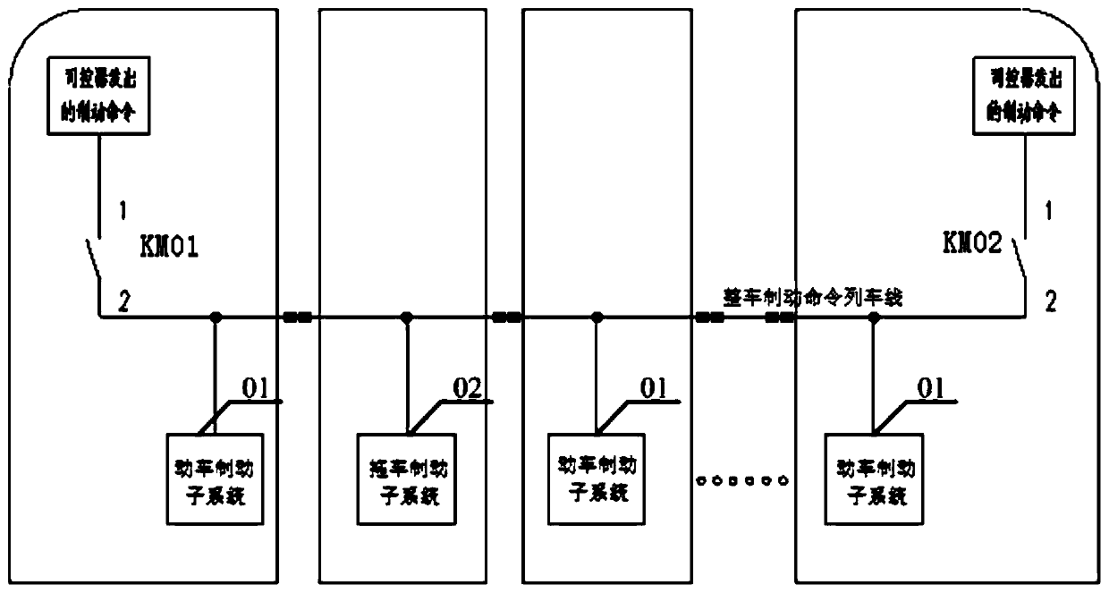
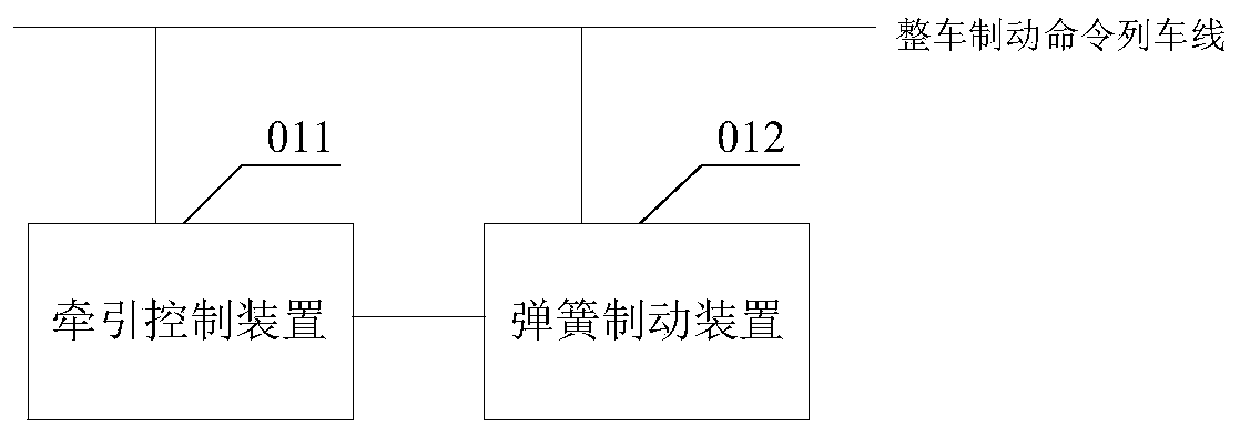
[0035] The core of this application is to provide a braking control system for rail vehicles. When the braking force provided by the traction control device is insufficient, the spring brake device can apply a passive hydraulic braking force to make up for the lack of braking force of the traction control device and reduce the coupling pressure. The force is applied to ensure the service life of the coupler; another core of the present application is to provide a rail vehicle including the above brake control system.

[0036] In order to make the purposes, technical solutions and advantages of the embodiments of the present application clearer, the technical solutions in the embodiments of the present application will be clearly and completely described below in conjunction with the drawings in the embodiments of the present application. Obviously, the described embodiments It is a part of the embodiments of this application, not all of them. Based on the embodiments in this a...


PUM


Abstract

The invention discloses a brake control system of a railway vehicle. The brake control system comprises bullet train brake subsystems in one-to-one correspondence with multiple section of bullet trains on a railway vehicle, each bullet train brake subsystem comprises: a traction control device, which is used for receiving a brake signal, outputting an electric braking force corresponding to the brake signal, and outputting an auxiliary brake signal when the electric braking force does not meet the braking force requirement corresponding to the brake signal; a spring brake device, which is usedfor outputting a braking force corresponding to an auxiliary brake signal when the auxiliary brake signal is received, and is also used for outputting a braking force corresponding to the brake signal when receiving the brake signal. When the braking force provided by the traction control device is insufficient, the spring brake device applies a passive hydraulic braking force to supplement the braking force lacking in the traction control device, the stress of a car coupler is reduced, and the service life of the car coupler is guaranteed. The invention further discloses a rail vehicle, which has the above beneficial effects.

Description

technical field [0001] The present application relates to the field of rail transportation, in particular to a rail vehicle and a braking control system thereof. Background technique [0002] In the original vehicle common braking design circuit, when the driver issues a common braking command, all single-section motor vehicle traction inverters of the motor vehicle will apply electric braking, and all single-section trailer active hydraulic braking systems will apply active braking. hydraulic braking force. The vehicles of each joint will produce corresponding braking force like this, and the coupler between vehicles only plays the effect of balancing braking force, and the force is not big. However, when a single train has a traction inverter failure, the corresponding single train will not be able to apply electric braking force when braking, so the braking force of the train will be determined by the compression force of the front coupler and the tension of the rear cou...

Claims


Application Information

Patent Timeline
Patent Type & Authority Applications(China)
IPC IPC(8): B60T8/17B60T13/66B60L7/26
CPCB60L7/26B60L2200/26B60T8/1705B60T13/662
Inventor 柳晓峰陈勇司尚卓聂文斌王丹梅
Owner ZHUZHOU ELECTRIC LOCOMOTIVE CO LTD
Why Eureka
Try Eureka