Parking brake control unit with remote release function

A technology of parking brake and control unit, applied in the direction of brakes, pneumatic brakes, brake transmission devices, etc., can solve the problems of locomotives that cannot be returned without fire, cannot guarantee relief, and cannot be returned without fire, and achieve guaranteed braking. relieving effect

Active Publication Date: 2016-11-02
KNORR BREMSE BRAKE EQUIP SUZHOU CO LTD
View PDF7 Cites 2 Cited by
  • Summary
  • Abstract
  • Description
  • Claims
  • Application Information

AI Technical Summary

Problems solved by technology

[0002] When the locomotive is in the no-fire loopback mode, it usually needs other vehicles to drag it. At this time, the operator needs to trigger the parking relief on the console. Apply the button to control the pulse. The solenoid valve is in the parking relief state. If the operator misoperates, there is no control pulse. If the solenoid valve is in the response state, there is no pressure input in the parking brake cylinder, and its relief cannot be guaranteed, so that the locomotive cannot be returned without fire.
In the prior art, another situation that usually occurs is that the pulse solenoid valve fails or the power supply for the pulse solenoid valve is in a state of no power supply, and the operator cannot control the state of the pulse solenoid valve, so that the locomotive cannot perform fire-free return

Method used


Image

  • Parking brake control unit with remote release function

Examples


Embodiment Construction

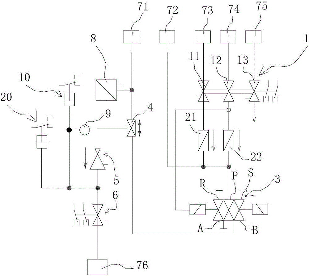
[0022] like figure 1 The parking brake unit shown includes a first stopcock 11 arranged on the pipeline for communicating with the main air duct 73, a second stopcock 12 for communicating with the brake duct 74, and a second stopcock 12 for communicating with the average duct. Three cocks 13, the parking brake unit also includes a pulse solenoid valve 3 arranged on the pipeline for communicating with the parking brake cylinder 76, the first cock 11, the second cock 12 and The pulse solenoid valve 3 is connected, and the pulse solenoid valve 3 includes a pilot control terminal for controlling the state of the pulse solenoid valve 3 according to the pressure input. The second plug 12 is also connected to the pulse solenoid valve. 3 pilot control terminal connected. The parking brake unit also includes a first check valve 21 and a second check valve 22, and the first check valve 21 is arranged between the first plug valve 11 and the pulse solenoid valve 3. On the pipeline, the ...


PUM


Abstract

The application discloses a parking brake control unit with a remote release function. The parking brake control unit comprises a first cock arranged on a pipeline and used for being communicated with a main air duct, a second cock used for being communicated with a brake pipe, and a third cock used for being communicated with an average pipe, and further comprises a pulse solenoid valve arranged on the pipeline and used for being communicated with a parking brake cylinder, wherein the first cock and the second cock are communicated with the pulse solenoid valve; the pulse solenoid valve comprises a pilot control terminal used for controlling the status of the pulse solenoid valve according to pressure input; the second cock is further communicated with the pilot control terminal of the pulse solenoid valve.

Description

technical field [0001] The present application relates to a parking brake control unit with remote release function. Background technique [0002] When the locomotive is in the no-fire loopback mode, it usually needs other vehicles to drag it. At this time, the operator needs to trigger the parking relief on the console. Apply the button to control the pulse. The solenoid valve is in the parking relief state. If the operator misoperates, there is no control pulse. If the solenoid valve is in a responsive state, there is no pressure input in the parking brake cylinder, and its relief cannot be guaranteed, so that the locomotive cannot be returned without fire. In the prior art, another situation that usually occurs is that the pulse solenoid valve fails or the power supply for the pulse solenoid valve is in a state of no power supply, and the operator cannot control the state of the pulse solenoid valve, so that the locomotive cannot perform fire-free return . Contents of ...

Claims


Application Information

Patent Timeline
Patent Type & Authority Applications(China)
IPC IPC(8): B61H11/10B60T13/70
CPCB60T13/70B61H11/10
Inventor 曼弗雷德·弗拉黄自立陆凤祥
Owner KNORR BREMSE BRAKE EQUIP SUZHOU CO LTD
Why Eureka
Try Eureka