Incremental launching technology of submerged cable-stayed floating tunnel

A floating tunnel and cable-stayed technology, which is applied in the field of underwater floating tunnels, can solve problems such as difficulty in predicting comfort and safety risks, displacement or shaking of the tunnel, and difficult construction, etc., to achieve improved docking accuracy and water-stopping effect , High construction efficiency and short construction period

Active Publication Date: 2020-06-09
CCCC THIRD HARBOR ENG +1
View PDF9 Cites 4 Cited by
  • Summary
  • Abstract
  • Description
  • Claims
  • Application Information

AI Technical Summary

Problems solved by technology

The buoy-type floating tunnel is suspended on the buoy on the water surface through anchor cables or anchor chains. The gravity of the tunnel is greater than the buoyancy, and the vertical direction is greatly affected by the fluctuation of the tide level; On the anchorage foundation below the bed, the gravity of the tunnel is less than the buoyancy, and the tunnel will displace or shake under the action of hydrodynamic forces; the pier-column type is actually a tunnel bridge supported on underwater pier columns, and the construction is difficult and expensive
Since the tunnel floats in the water, the installation and construction of the tunnel is affected by wind, waves, currents and ship waves. The underwater positioning of the three types of tunnels and the underwater or underwater docking construction are very difficult, and the comfort and safety of the underwater operation period Risks are unpredictable

Method used


Image

  • Incremental launching technology of submerged cable-stayed floating tunnel
  • Incremental launching technology of submerged cable-stayed floating tunnel
  • Incremental launching technology of submerged cable-stayed floating tunnel

Examples


Embodiment Construction

[0052] The present invention will be further described below in conjunction with accompanying drawing.

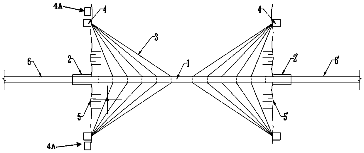
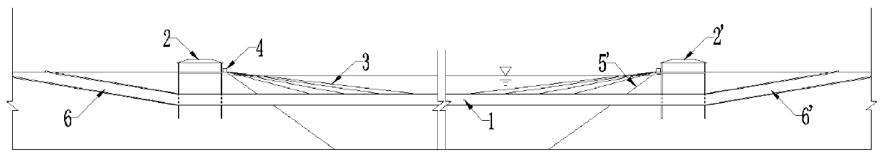
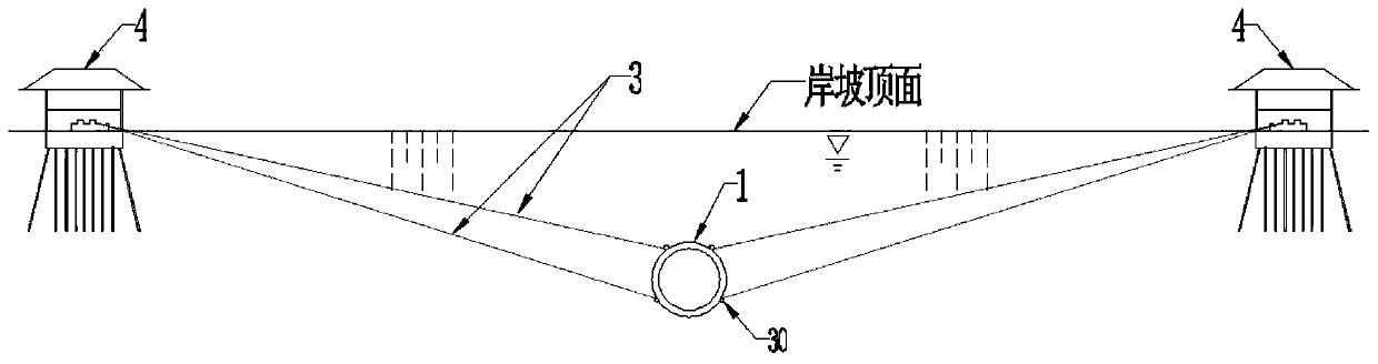
[0053] see Figure 1 to Figure 10 , the jacking process of the underwater cable-stayed floating tunnel of the present invention, the applicable floating tunnel includes the tunnel body, the pushing side shore structure 2, the receiving side shore structure 2', the cable anchorage system and the buoyant weight ratio adjustment system; Among them, the tunnel body includes the floating tunnel 1 in the water, the land slope tunnel 6 on the pushing side and the slope tunnel 6' on the receiving side; On the coast 5 and the coast 5' on the receiving side; the water-facing end of the land slope tunnel 6 on the pushing side and the water-facing end of the land slope tunnel 6' on the receiving side are connected to the shore structure 2 on the pushing side and the shore on the receiving side in one-to-one correspondence The backwater end of the structure 2' is connected; the underwa...


PUM


Abstract

The invention discloses incremental launching technology of a submerged cable-stayed floating tunnel. The incremental launching technology of the submerged cable-stayed floating tunnel comprises the following steps that all pipe joints of the submerged floating tunnel in a land area prefabrication yard are prefabricated, then the pipe joints are transported to an incremental launching side shore connecting structure through a land area slope tunnel, secondary outfitting is successively carried out, the pipe joints are docked with the subsequent pipe joints and sealed into water, then the pipejoints are in a receiving side shore connecting structure section by section in an incremental launching manner; stay cables are installed on the pipe joints one by one along with incremental launching and pulled to a stay cable anchorage pier; and after incremental launching is completed, concrete on the outer surface of the pipe joints at both ends of the submerged floating tunnel is poured intothe incremental launching side shore connecting structure and the receiving side shore connecting structure, the consolidation of the pipe joints at both ends of the submerged floating tunnel is completed, then the buoyant weight ratio can be adjusted by adjusting the ballast water volume in each pipe joint, and the cable force adjustment of the stay cable is carried out and the sealing anchor iscarried out at the stay cable anchorage pier. The incremental launching technology of the submerged cable-stayed floating tunnel has little influence by wind, wave, current, ship traveling wave and the like, greatly reduces the safety risk of man-machine for offshore construction, and has high construction efficiency and short construction period.

Description

technical field [0001] The invention relates to an underwater suspension tunnel, in particular to a jacking process for an underwater cable-stayed suspension tunnel. Background technique [0002] The submerged floating tunnel, the English name is "Submerged Floating Tunnel", referred to as "SFT". In Italy, it is also called "Archimedes bridge", or "PDA" bridge for short. Generally, it consists of a tubular body floating at a certain depth in the water (the space of the tubular body is large enough to meet the requirements of road and railway traffic), a support system (anchor cables anchored on the seabed foundation, piers or floating boxes on the water) and It is composed of structures on both sides of the river. It is a new type of structure that means of transportation across the two banks separated by deep water. It is suitable for all means of transportation that need to pass through the water. It can pass trains, cars, small motor vehicles and pedestrians, and can al...

Claims


Application Information

Patent Timeline
Patent Type & Authority Applications(China)
IPC IPC(8): E02D29/067
CPCE02D29/067E02D2250/0061E02D2250/0092E02D29/07E02D29/063
Inventor 徐立新郑荣平赵辉孙洪春莫亚思孙旭邹星罗浩
Owner CCCC THIRD HARBOR ENG
Why Eureka
Try Eureka