Indoor decoration device

A technology for interior decoration and painting, applied in mixers with rotary stirring devices, transportation and packaging, mixers, etc., can solve the problems of high time cost, material dripping, uneven paint, etc., and achieve balanced feeding methods. Avoid hidden dangers, the effect of large displacement range

Active Publication Date: 2020-06-26
HENAN INST OF SCI & TECH
View PDF12 Cites 1 Cited by
  • Summary
  • Abstract
  • Description
  • Claims
  • Application Information

AI Technical Summary

Problems solved by technology

[0012] The purpose of the present invention is to solve the problems of uneven coating,

Method used


Image

  • Indoor decoration device
  • Indoor decoration device
  • Indoor decoration device

Examples


Example Embodiment

[0042] Example 1

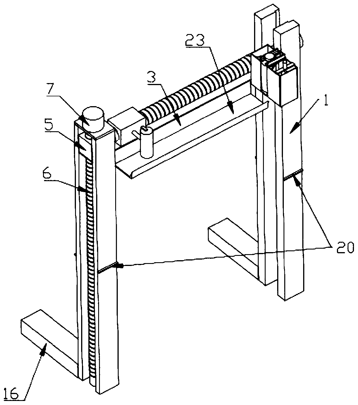
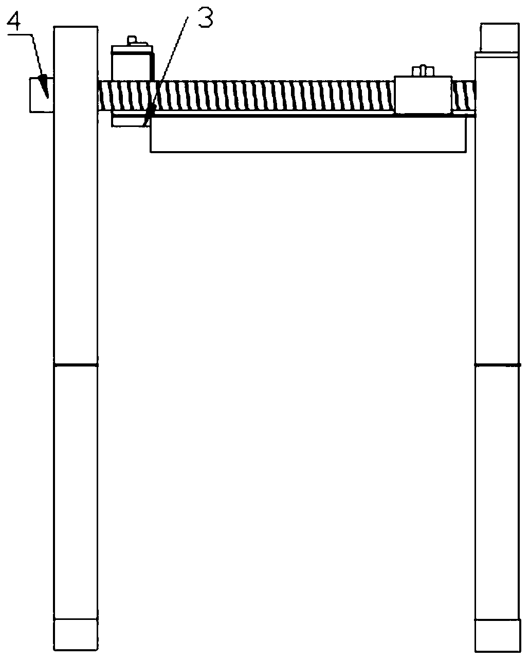
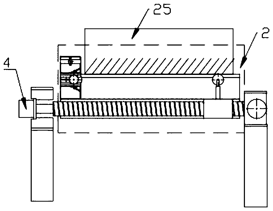
[0043] An interior decoration device, see Figure 1 to Figure 10 , including the fixing block 3 of the painting mechanism 2 installed on the screw type lifting frame 1, the painting mechanism 2 is installed on the fixing block 3, the displacement line is parallel to the horizontal plane, and one end of the screw is installed with a transverse motor 4. There is a transverse sliding block on the lead screw, and the transverse sliding block is connected to the coating mechanism. A pressure regulating device is provided between the coating roller 24 of the coating mechanism 2 and the transverse sliding block to make the coating mechanism 2 close to the treated On the wall, an automatic feeding mechanism is installed on the side of the fixing block 3 away from the horizontal motor 4;

[0044] The lead screw lift frame 1 includes a slider 5, a vertical slide rail that limits the freedom of the slider 5, and a vertical lead screw 6 that drives the slider 5 to move...

Example Embodiment

[0052] Example 2

[0053] The principle of this embodiment is the same as that of Embodiment 1, and the specific difference is: Figure 7 , the width of the automatic feeding mechanism is reduced to prevent it from interfering with the painting roller 24, and it does not affect the painting of the wall. Compared with the design in Example 1, where a part of the equipment is located at the door frame, the use space of this design is more. big.

Example Embodiment

[0054] Example 3

[0055] The principle of this embodiment is the same as that of Embodiment 1, and the specific difference is: Figure 9 , the top support plate is provided with a rocker 17, and the power source of the friction roller is replaced by manual, which reduces the cost of equipment coordination. During the process of outward extrusion, proper bidirectional rotation can promote the elastic baffle 10 to be in the best position. Location.


PUM


Abstract

The invention relates to the field of home decoration equipment, in particular to an indoor decoration device. The indoor decoration device solves the problems that a painting device is low in automation degree and working efficiency in indoor decoration in the prior art. The indoor decoration device comprises a fixing block for a painting mechanism, wherein the fixing block is arranged on a screwrod type lifting frame; the painting mechanism is arranged on the fixing block; a displacement line is parallel to the horizontal plane; a horizontal motor is arranged at one end of a screw rod; a horizontal sliding block is arranged on the screw rod and is connected with the painting mechanism; a pressure adjusting device is arranged between a painting roller of the painting mechanism and the horizontal sliding block in order to enable the painting mechanism to be attached to a treated wall tightly; and an automatic feeding mechanism is arranged at one side, away from the horizontal motor, of the fixing block. The indoor decoration device has the advantages that the position of the painting roller can be adjusted, and the adjusting frequency in working is reduced; and excessive feeding is avoided, the pressure between the painting roller and the wall is fixed, and the uniform painting is achieved.

Description

technical field [0001] The invention relates to the field of interior decoration devices, in particular to an interior decoration device. Background technique [0002] Interior decoration, including the practicability and comfort of interior space organization, interface treatment, furniture, lighting, greening layout, etc., the rationality and economy of project budget and cost; the sturdiness and safety of structure and materials; The scientificity and rationality of the practical application of interior care, color design and material selection of cross-section treatment, mainly including the laying of water and electricity pipelines, the painting of the walls, the design of the bottom line of the corners and the further installation design. At this stage, the painting process of the wall is mostly done manually. [0003] In the published patent documents, the application number is 201811348289.0, which is called a patent for a small wall paint applicator. By arranging a...

Claims


Application Information

Patent Timeline
IPC IPC(8): E04F21/08B01F7/16
CPCE04F21/08B01F27/80
Inventor 申迎迎刘晨洁
Owner HENAN INST OF SCI & TECH
Why Eureka
Try Eureka