Angle iron assembly device

A technology for assembling devices and angle irons, applied in auxiliary devices, auxiliary welding equipment, welding/welding/cutting items, etc., can solve the problems of high requirements for mechanical automation, positioning accuracy affecting the quality of finished products, and increasing the difficulty of research and development. Save manpower, meet the needs of automated production, improve production efficiency and product quality

Pending Publication Date: 2020-07-03
苏州光彩钢板仓有限公司
View PDF0 Cites 1 Cited by
  • Summary
  • Abstract
  • Description
  • Claims
  • Application Information

AI Technical Summary

Problems solved by technology

However, in the face of this special assembly requirement, the position of the angle iron is required to be high, and a series of actions such as feeding, pre-splicing, conveying, and welding require a high degree of mechanical automation. Positioning accuracy, etc. will affect the quality of finished products, increasing the difficulty of research and development
The existing manipulator grabbing method is difficult to meet the position accuracy requirements and is not suitable for this working condition, which will affect the subsequent welding

Method used


Image

  • Angle iron assembly device
  • Angle iron assembly device
  • Angle iron assembly device

Examples


Embodiment Construction

[0027] The technical solutions of the present invention will be clearly and completely described below in conjunction with the accompanying drawings.

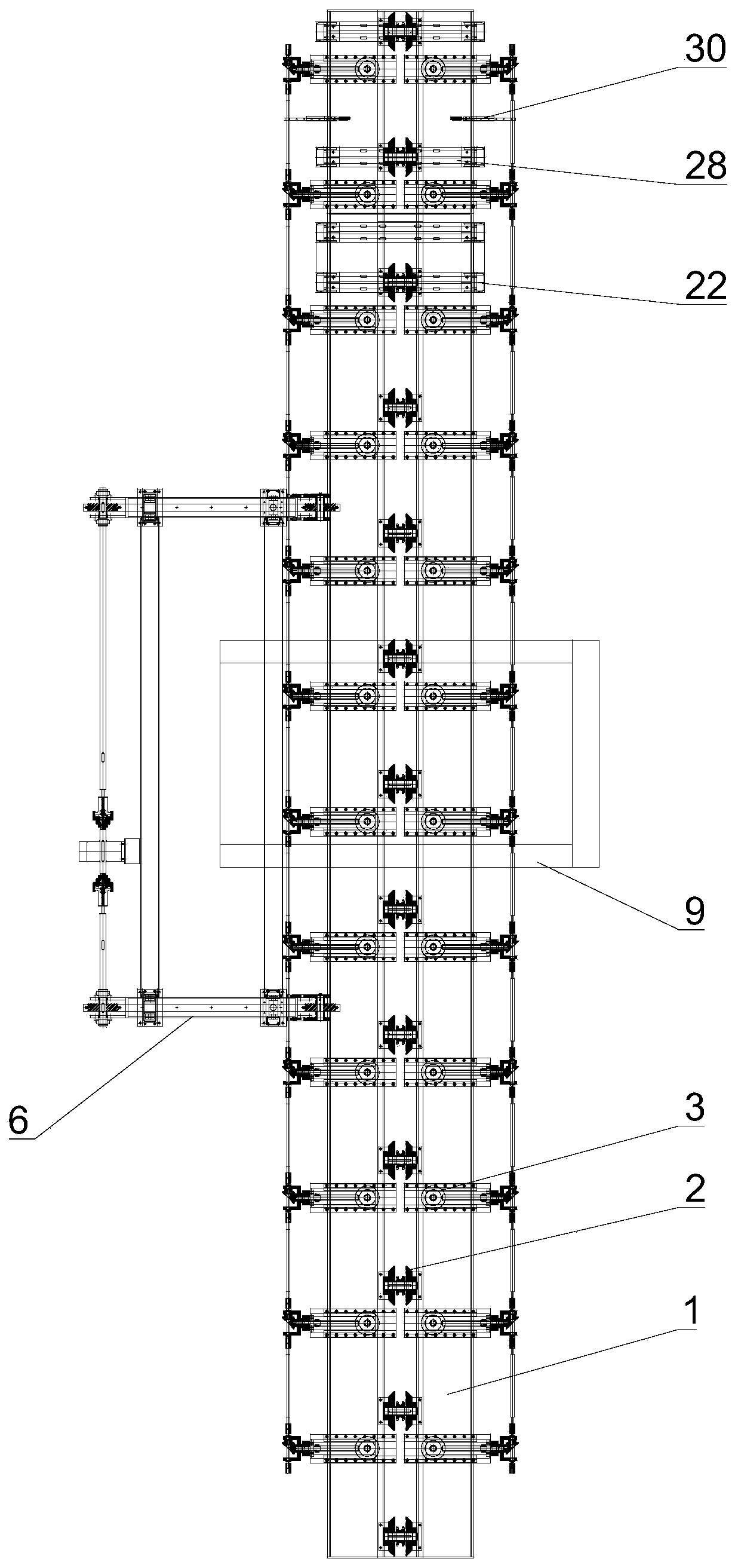
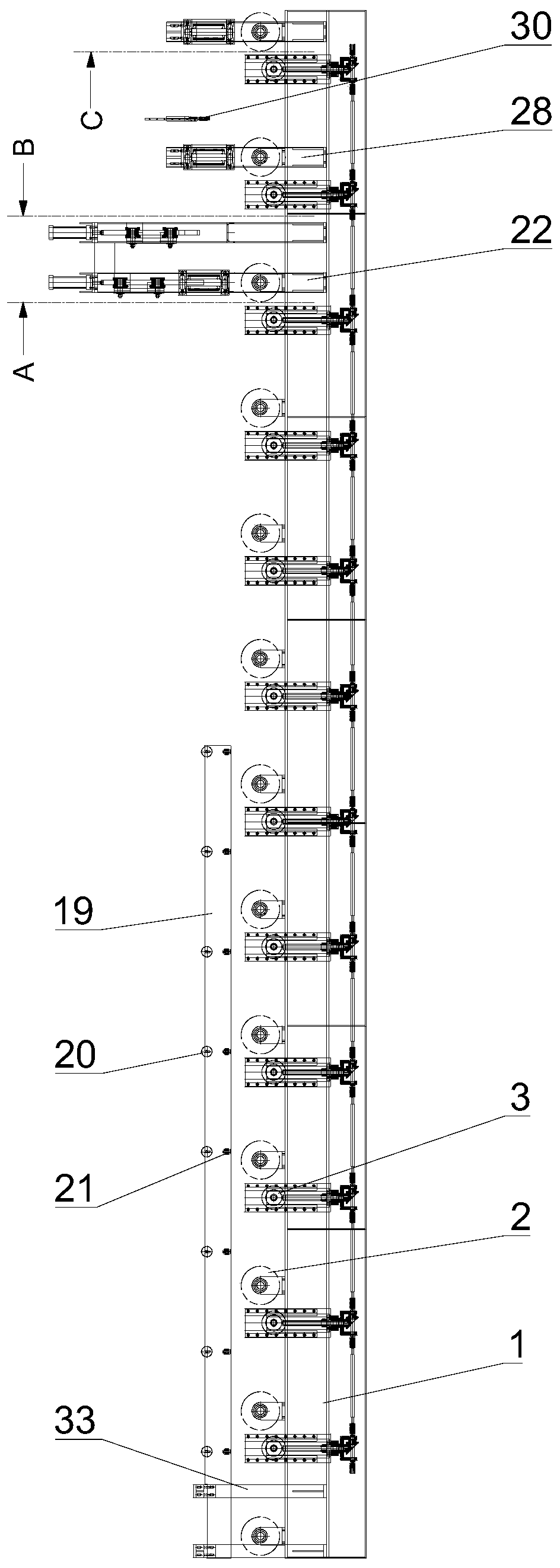
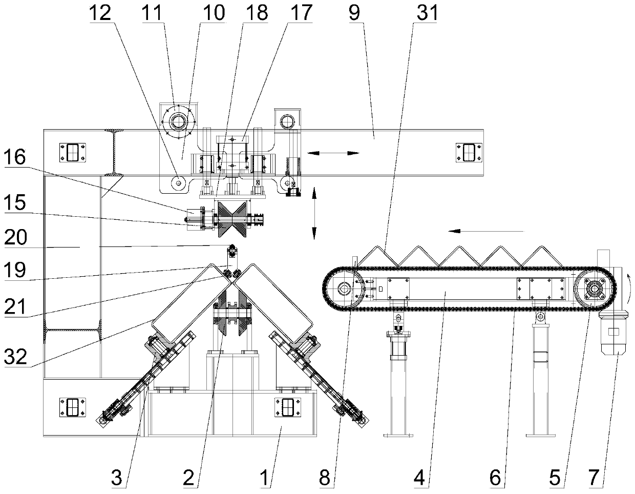
[0028] see Figures 1 to 7 As shown, this embodiment provides an angle iron assembling device for assembling two "L"-shaped spliced ​​square tubes 32 and angle irons 31, which includes a support seat 1, a feeding mechanism, a limit mechanism and a welding mechanism.

[0029] Due to the specific splicing shape, the two square tubes 32 need to be fixed first, and then combined with the angle iron 31 . Therefore, the supporting base 1 is provided with conveying rollers 2 and guide assemblies located on both sides of the conveying rollers 2. Several conveying rollers 2 are arranged at intervals along the length direction of the supporting base 1 to form a production conveying line. The guiding assemblies include guide wheels 3 , the conveying roller 2 comprises two tapered surface wheels inclined to both sides, the bottom surface...


PUM


Abstract

The invention discloses an angle iron assembly device. The angle iron assembly device comprises a supporting base, a loading mechanism, a limiting mechanism and a welding mechanism, wherein a conveying roller and guide assemblies at the two sides of the conveying roller are arranged on the supporting base; the conveying rollers are arranged in a spaced mode in a length direction of the supportingbase to form a production conveyor line; each guide assembly comprises a guide wheel; each conveying roller comprises two tapered-surface wheels with tapered surfaces tilting towards two sides; the bottom surfaces of two square tubes are supported by corresponding guide wheels, and the inner side surfaces of the two square tubes cling to the tapered surfaces of the corresponding tapered-surface wheels; the loading mechanism comprises a transfer frame positioned above the supporting base, and the transfer frame comprises a rail beam, a cross travelling trolley capable of moving and lifting backand forth is arranged on the rail beam, and a taking roller is arranged on the cross travelling trolley; the taking roller comprises two magnetic attraction wheels which are clung to each other and are provided with tapered surfaces tilting towards the middle, so that the taking roller is adaptive to the outer surface of the angle iron; the limiting mechanism is used for calibrating and keeping assembly states of the angle iron and two square tubes; and the welding mechanism comprises a welding gun which is arranged at a joint part of angle iron and two square irons under an assembly state.

Description

technical field [0001] The invention relates to the technical field of section steel assembling, in particular to an angle iron assembling device. Background technique [0002] Steel structure is a very important type of structure in modern buildings. It has many advantages such as high strength, light weight, good rigidity, and strong toughness, and is widely used. In the face of various construction needs, there are situations where two square tubes need to be spliced ​​into an "L" shape. At this time, the edges of the two square tubes are close together to form a corner, and the connection strength is poor, so it is difficult to ensure the structure stability, so it is necessary to set another angle iron to form a complete "L" shaped steel, such as Figure 8 shown. However, in the face of this special assembly requirement, the positional requirements of the angle iron are relatively high, and a series of actions such as feeding, pre-splicing, conveying, and welding requi...

Claims


Application Information

Patent Timeline
Patent Type & Authority Applications(China)
IPC IPC(8): B23P19/00B23K37/04B23K37/02
CPCB23K37/02B23K37/0443B23K2103/04B23P19/00B23P19/001
Inventor 易书云易仕桂陆照俊周越华殷科
Owner 苏州光彩钢板仓有限公司
Why Eureka
Try Eureka