Fuel injector fixing structure

A fixed structure and fuel injector technology, which is applied in the direction of machines/engines, fuel injection devices, engine components, etc., can solve problems such as the difficulty of fixing the fuel injector and reduce the weight of the cylinder head, and achieve weight reduction, high adaptability, and easy installation Solid and stable effect

Pending Publication Date: 2020-07-03
GUANGXI YUCHAI MASCH CO LTD
View PDF1 Cites 0 Cited by
  • Summary
  • Abstract
  • Description
  • Claims
  • Application Information

AI Technical Summary

Problems solved by technology

[0004] The invention provides a fuel injector fixing structure, which aims to solve the problem of difficult fixing of the fuel injector due to structural changes in the process of engine design and development, raise the support surface of the fuel injector pressure block, and ensure the compact design of the cylinder head cover. Effectively reduce the weight of the cylinder head

Method used


Image

  • Fuel injector fixing structure
  • Fuel injector fixing structure
  • Fuel injector fixing structure

Examples


Embodiment 1

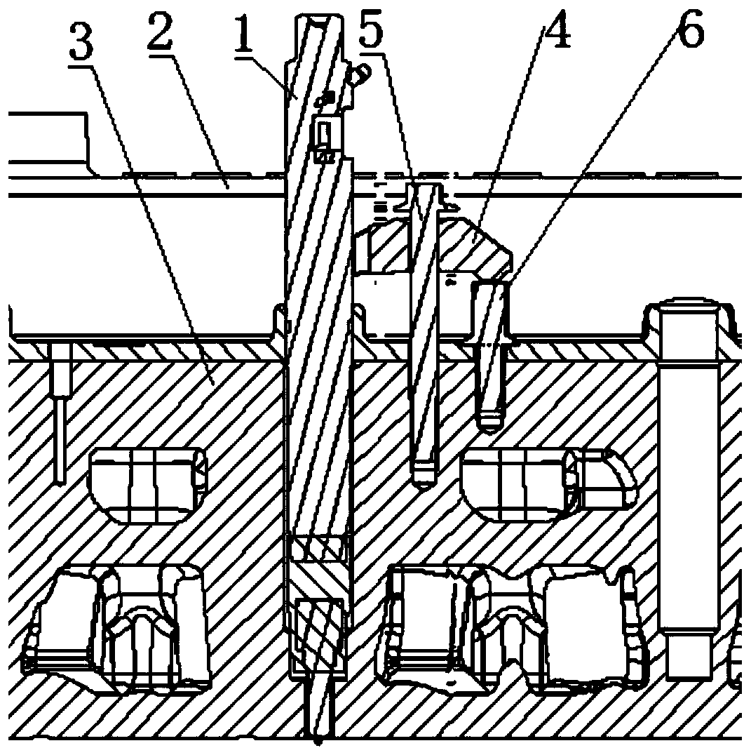
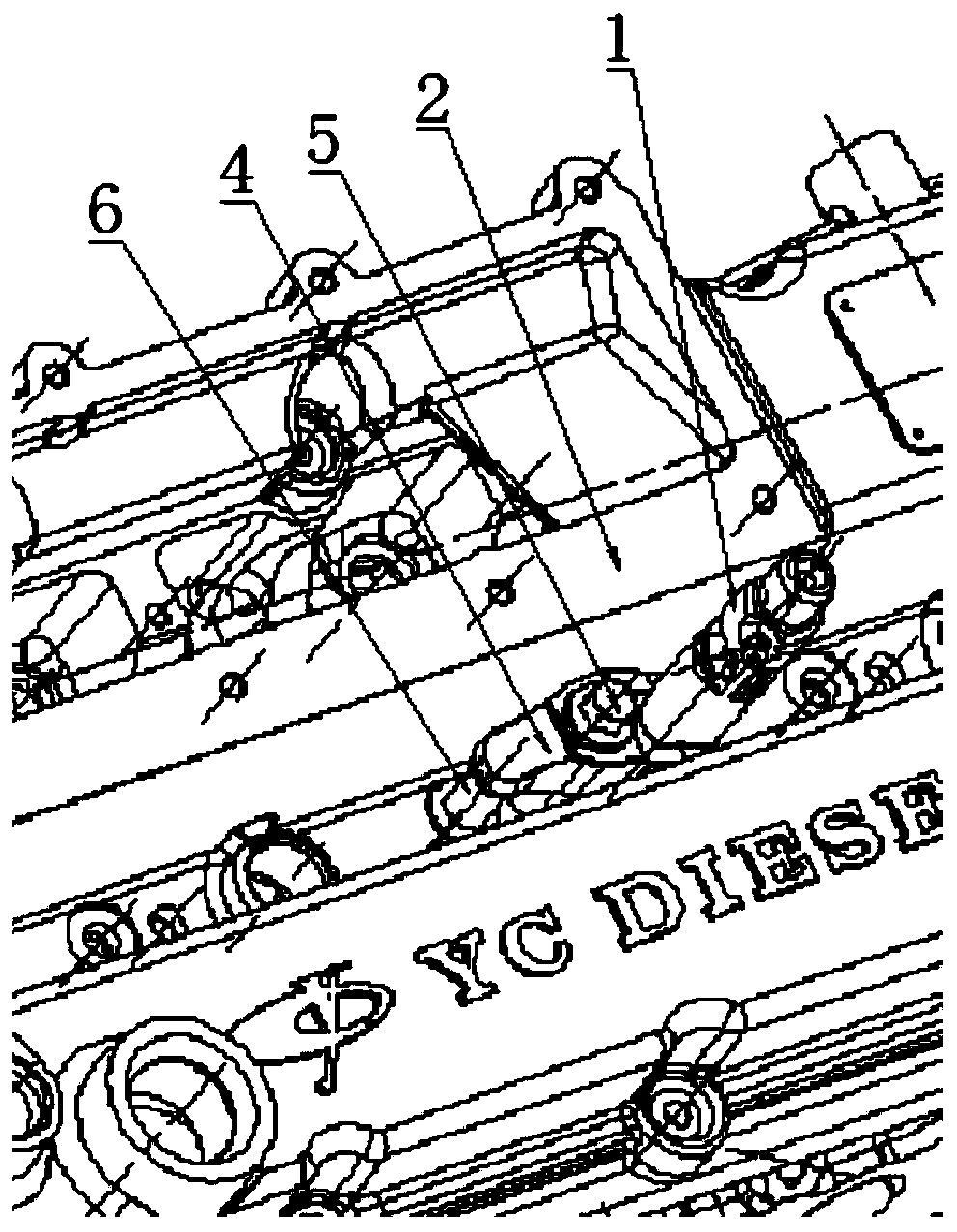
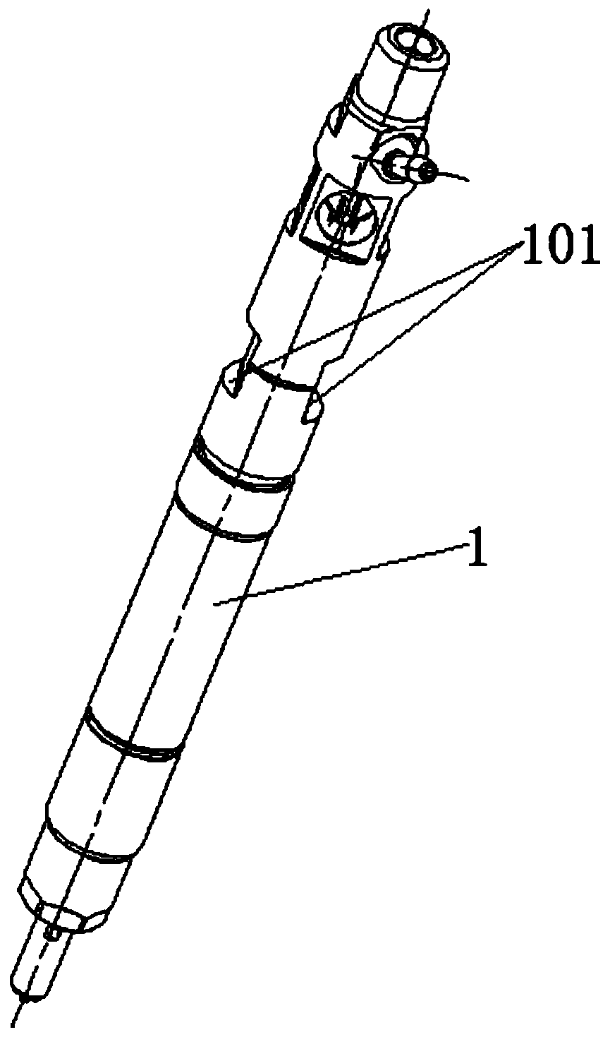
[0020] Such as figure 1 with figure 2 As shown, this embodiment is used to install the fuel injector 1 on the cylinder head 3, including a pressure block 4 with one end abutting against the mounting surface 101 on the fuel injector 1, and one end abutting against the middle of the pressure block 4 The compression bolt 5 on the surface and the other end threaded with the cylinder head 3 also includes a support element 6 threaded with the cylinder head 3 , the top of the support element 6 abuts against the bottom of the other end of the pressure block 4 .

[0021] This embodiment adopts the design structure of padding the high-pressure block 4, that is, the top of the support element 6 is used as a supporting surface to pad the high-pressure block 4, which avoids the direct installation of the pressure block 4 on the cylinder head 3 in the prior art, and the installation is firm and stable. to fix the cylinder head cover 2; at the same time, it can reduce the height of the cyl...

Embodiment 2

[0023] Such as figure 1 with figure 2 As shown, this embodiment is applied to an engine with a camshaft double overhead structure. When the cylinder head cover 2 of this model is arranged, there will be a situation that the two sides are high and the middle is low, and the middle low part is the installation part of the fuel injector 1. , this embodiment is used to install the fuel injector 1 on the cylinder head 3, including a pressure block 4 with one end abutting against the mounting surface 101 on the fuel injector 1, one end abutting against the middle upper surface of the pressure block 4 and The other end is connected with the compression bolt 5 of the cylinder head 3, that is, the middle part of the pressure block 4 has a through hole, and the threaded part of the compression bolt 5 passes through the through hole and is connected with the cylinder head 3; The support element 6 is threadedly connected to the cover 3 , and the top of the support element 6 abuts agains...


PUM


Abstract

The invention relates to the technical field of fuel injectors, in particular to a fuel injector fixing structure. The fuel injector fixing structure comprises a pressing block which one end is abutted against an installing surface on an fuel injector and a pressing bolt with one end abutting against the upper surface of the middle of the pressing block and the other end is in threaded connectionwith a cylinder head, and further comprises a supporting element in threaded connection with the cylinder head, wherein the top of the supporting element abuts against the bottom of the other end of the pressing block. According to the fuel injector fixing structure, the problem that the fuel injector is difficult to fix due to structural change in a design and development process of an engine issolved, the supporting surface of the fuel injector pressing block is raised, the compactness design of a cylinder head cover is guaranteed, and the weight of the cylinder head is effectively reduced.

Description

technical field [0001] The invention relates to the technical field of fuel injectors, in particular to a fuel injector fixing structure. Background technique [0002] In the design and development of diesel engines, the installation of injectors is a problem that needs to be considered in design and development, involving the sealing of lubricating oil and gas. During the engine design process, due to product structure limitations, there are some structures with recessed injector mounting surfaces, which are difficult to install and design for such structures. [0003] In the prior art, there is a structure in which the fuel injector is installed in the form of a briquetting block, such as the Chinese patent CN101245752A, which discloses a pressing device for an electronically controlled fuel injector of a diesel engine, including two ends that are respectively pressed on the fuel injector and the cylinder head There is a pressing block between the pressing block and the c...

Claims


Application Information

Patent Timeline
Patent Type & Authority Applications(China)
IPC IPC(8): F02M61/14
CPCF02M61/14
Inventor 刘显宏董家枝冯世光覃海玉蒙小聪
Owner GUANGXI YUCHAI MASCH CO LTD
Why Eureka
Try Eureka