Electro-hydraulic control pressure suppression system and method for hydraulic support column

A hydraulic support column, electro-hydraulic control technology, applied in the direction of mine roof support, support/support, earthwork drilling, etc. Low work efficiency and other problems, to achieve the effect of improving the success rate of dismantling, solving the problem of safety accidents, and improving the efficiency of dismantling

Active Publication Date: 2019-06-18
CHINA SHENHUA ENERGY CO LTD +1
View PDF5 Cites 0 Cited by
  • Summary
  • Abstract
  • Description
  • Claims
  • Application Information

AI Technical Summary

Problems solved by technology

When dismantling the guide sleeve of the middle cylinder, the middle cylinder will rotate in the outer cylinder, resulting in a serious power loss of the hydraulic motor of the column dismantling machine, which cannot meet the disassembly torque of the guide sleeve of the middle cylinder, and the disassembly work efficiency is low, and the disassembly success rate is low

Method used


Image

  • Electro-hydraulic control pressure suppression system and method for hydraulic support column
  • Electro-hydraulic control pressure suppression system and method for hydraulic support column
  • Electro-hydraulic control pressure suppression system and method for hydraulic support column

Examples


Embodiment Construction

[0020] The technical solutions of the present invention will be described in detail below in conjunction with the accompanying drawings and specific embodiments.

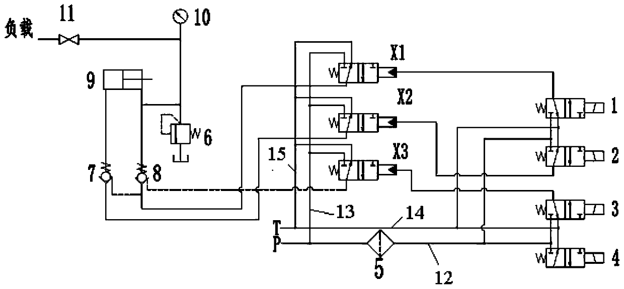
[0021] figure 1 It shows the control principle diagram of the electro-hydraulic control pressure holding system of the embodiment of the present invention, as figure 1 As shown, the electro-hydraulic control pressure holding system includes the main liquid inlet pipeline P, the main liquid return pipeline T, the supercharger 9, the first hydraulic control check valve 8, the second hydraulic control check valve 7, the first hydraulic control two-way One-position three-way reversing valve X1, the second hydraulically controlled two-position three-way reversing valve X2, the first electromagnetic reversing valve 1 and the second electromagnetic reversing valve 2.

[0022] Wherein, the main liquid inlet pipeline P includes a first branch 12 and a second branch 13 . The main liquid return pipeline T includes a third br...


PUM


Abstract

The embodiment of the invention discloses an electro-hydraulic control pressure shutoff system used for a hydraulic support vertical column. The electro-hydraulic control pressure shutoff system comprises a liquid inlet main pipeline, a liquid returning main pipeline, a pressurizer, two hydraulic control one-way valves, two hydraulic control two-position three-way reversing valves and two electromagnetic reversing valves. The liquid inlet main pipeline comprises a first branch and a second branch; the liquid returning main pipeline comprises a third branch and a fourth branch; the first branch is connected with inlets of the two electromagnetic reversing valves; emittings of the two electromagnetic reversing valves are connected with control openings of the two hydraulic control two-position three-way reversing valves; oil returning openings of the two electromagnetic reversing valves are connected with the third branch; the second branch is connected with inlets of the two hydraulic control two-position three-way reversing valves; oil returning openings of the two hydraulic control two-position three-way reversing valves are connected with the fourth branch; and an emitting of the pressurizer used for being connected with an annular cavity. The embodiment of the invention discloses an electro-hydraulic control pressure shutoff method used for the hydraulic support vertical column. By utilizing the electro-hydraulic control pressure shutoff system and method used for the hydraulic support vertical column, the disassembling efficiency of a middle cylinder guide sleeve can be improved.

Description

technical field [0001] The embodiment of the present invention relates to the field of coal mine electromechanical technology, in particular to an electro-hydraulic control pressure holding system and method for a hydraulic support column. Background technique [0002] In recent years, with the rapid development of my country's coal mine production capacity, the application of hydraulic supports in fully mechanized mining work has become more and more extensive, and the requirements for the support force and working resistance of hydraulic supports are increasing. The requirements for safety, reliability and economy are also getting higher and higher. The hydraulic support column is the main load-bearing part that bears the pressure of the roof, and requires strict sealing performance and strength for the outer cylinder, the middle cylinder guide sleeve and the piston. When the piston seal of the outer cylinder and the middle cylinder, the seal of the guide sleeve or the wea...

Claims


Application Information

Patent Timeline
Patent Type & Authority Patents(China)
IPC IPC(8): F15B11/08F15B13/04F15B3/00E21D15/51E21D23/26
CPCE21D15/512E21D23/26F15B3/00F15B11/08F15B13/0401
Inventor 刘军乐鲍建军暴红星王艳军曹世峰燕冬平
Owner CHINA SHENHUA ENERGY CO LTD
Why Eureka
Try Eureka