Rapid clamping device for laser tin soldering of electric ignition head

A clamping device and laser welding technology, used in auxiliary devices, welding equipment, metal processing equipment, etc., can solve the problems of control accuracy and service life affecting the fixing effect and accuracy of solder parts, and improve clamping efficiency and synchronization. flexibility, high positional accuracy, high degree of automation and efficiency

Active Publication Date: 2021-03-12
CHUANNAN MACHINERY PLANT CHINA ASTRONAUTIC SCI &TECH GROUP CORP
View PDF10 Cites 0 Cited by
  • Summary
  • Abstract
  • Description
  • Claims
  • Application Information

AI Technical Summary

Problems solved by technology

However, this tool realizes the flip limit through the connector to pressurize and limit the solder parts on the bottom plate. The control accuracy and service life of the connector affect the fixing effect and accuracy of the solder parts

Method used


Image

  • Rapid clamping device for laser tin soldering of electric ignition head
  • Rapid clamping device for laser tin soldering of electric ignition head
  • Rapid clamping device for laser tin soldering of electric ignition head

Examples


Embodiment

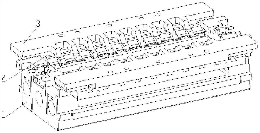
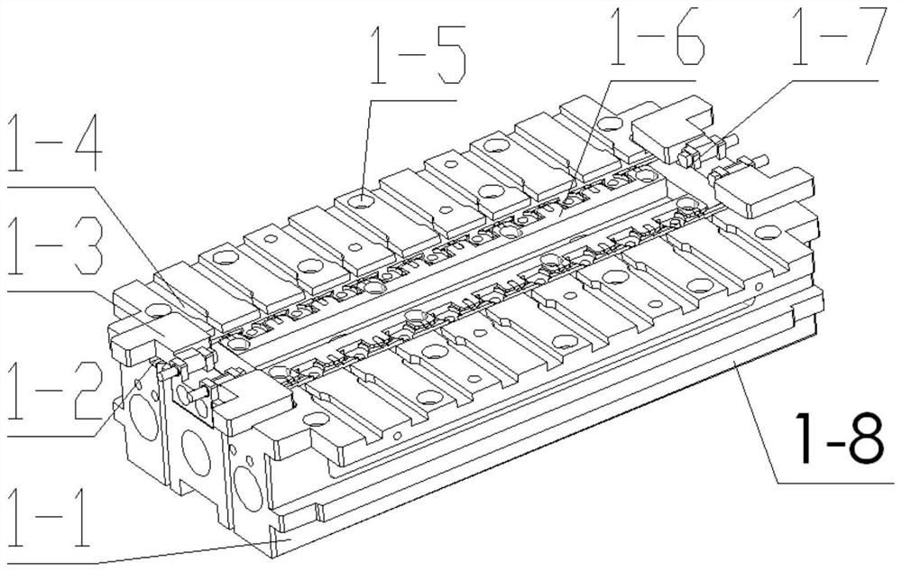
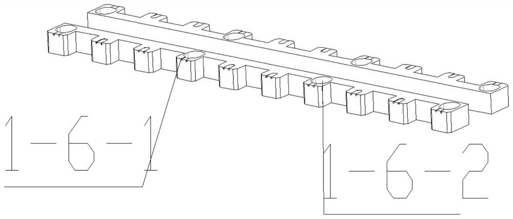
[0054]The base assembly 1 includes: a limiting step 1-1, a bridge drawing tank 1-2, a wire pressure block 1-3, a power-proof head limit fixing groove 1-4, a first magnetic suction hole 1-5 , The wire adjustment baffle 1-6, the wire block rotating shaft 1-7. The base 1-8 is a rectangular structure, the top symmetry distribution two-discharged head limit fixing groove 1-4, on the top surface, the limit fixed groove 1-4 is small, the central to the end is wider The width at the opening is about two wires and the distance is row, and the overall shrinkage is shaped. The limit fixed slot is the first magnetic suction hole 1-5, and the fault is distributed on the surface, and the depth is 3 to 5 mm. The front position of the limit fixed slot is close to the base 1-8 is in the middle position as the wire adjustment baffle 1-6, including wire core limit apertures 1-6-1, wire adjustment baffle position fixing hole 1-6-2, guide wire core The line limit hole 1-6-1 has a diameter of 0.2 to 1 mm...


PUM

PropertyMeasurementUnit
depthaaaaaaaaaa
diameteraaaaaaaaaa

Abstract

A rapid clamping device for laser tin soldering of an electric ignition head comprises a base assembly, an electric ignition head pressurizing plate and a bridge wire pressurizing block. Two columns and N rows of electric ignition head limiting fixing grooves are arrayed in the base assembly, and the electric ignition head limiting fixing grooves are used for containing electric ignition head forked wires. A bridge wire pulling and covering groove is machined in the base assembly in the length direction of the cuboid and used for containing a bridge wire. Bridge wire fixing mechanisms are arranged at the two ends of the base assembly correspondingly and used for fixing the two ends of the bridge wire. The electric ignition head forked wires are pressed and fixed by the electric ignition head pressurizing plate through a plurality of electric ignition head pressurizing claws, and the bridge wire is pressed and fixed by the bridge wire pressurizing block through a plurality of bridge wire pressurizing claws; the pressurizing claws of the electric ignition head pressurizing plate and the bridge wire pressurizing claws of the bridge wire pressurizing block are arranged at intervals; and the base assembly and the electric ignition head pressurizing plate are connected and fixed through magnets, and the electric ignition head pressurizing plate and the bridge wire pressurizing blockare connected and fixed through magnets. Rapid clamping of laser tin soldering can be achieved by the rapid clamping device for laser tin soldering of the electric ignition head, and the positioning precision is high.

Description

Technical field[0001]The present invention relates to a rapid assembly apparatus for electricity fire head laser solder solder, in particular to electricity fire head laser solder.Background technique[0002]Bridge welding is a high-precision operation, usually welding bridge size is 0.024mm ~ 0.09mm, mainly reflected in the finest bridge and wire core line positioning accuracy is difficult to ensure the length of the bridge wire and solder joints The size is ensured to ensure the bridge resistance in a reasonable range. Prior to the welding of the bridge, if it is possible to improve the positional accuracy of the wire core wire itself, it will greatly reduce the difficulty of subsequent bridge positioning. Patent CN210412958U discloses a common mode electrical painted wire solder tool, by increasing the equal spacing on a long square plate, a plurality of square pass grooves are formed, and in the groove is placed to be welded to be welded, due to the limit of the groove. Weakened, ...

Claims


Application Information

Patent Timeline
Patent Type & Authority Applications(China)
IPC IPC(8): B23K3/08B23K3/00
CPCB23K3/08B23K3/087B23K3/00
Inventor 阙刚夏先友丁冲黄凡泰张彩星詹亮杨华祥李良
Owner CHUANNAN MACHINERY PLANT CHINA ASTRONAUTIC SCI &TECH GROUP CORP
Why Eureka
Try Eureka