Die cutting waste removal equipment for printshop

A printing factory and die-cutting technology, which is applied in the field of die-cutting waste removal equipment for printing factories, can solve problems such as low efficiency and high labor intensity, and achieve the effect of reducing labor intensity and reducing occupied space

Inactive Publication Date: 2020-08-25
赣州惠彩印刷有限公司
View PDF8 Cites 0 Cited by
  • Summary
  • Abstract
  • Description
  • Claims
  • Application Information

AI Technical Summary

Problems solved by technology

[0005] In order to overcome the disadvantages of low efficiency and high labor intensity in cutting the waste pieces on the die-cut paper shells with a hand-held electric cutting machine for a long time, the technical problem to be solved by the present invention is to provide a method that can quickly Waste cleaning, die-cutting waste cleaning equipment for printing plants that can reduce labor intensity of workers

Method used


Image

  • Die cutting waste removal equipment for printshop
  • Die cutting waste removal equipment for printshop
  • Die cutting waste removal equipment for printshop

Examples


Embodiment 1

[0028] A kind of die-cut waste stripping equipment for printing factory, such as Figure 1-6 As shown, it includes base 1, roller 2 and handle frame 3, and also includes sliding column 4, lifting frame 5, sliding frame 6, pull rod 7, rejecting mechanism 8 and pressing mechanism 9, and the four corners at the bottom of base 1 are all The roller 2 is connected in a rotating manner, the handle frame 3 is connected to the top and rear side of the base 1, and the four corners of the top of the base 1 are connected to the sliding posts 4, and the sliding posts 4 are located on the front side of the handle frame 3, and the front side of the handle frame 3 Sliding connection has two sliding frames 6, and the two sliding frames 6 are left and right symmetrical, and a lifting frame 5 is connected between the front sides of the two sliding frames 6, and the lifting frame 5 is set on the sliding column 4, and the two sliding frames 6 A pull rod 7 is connected between the inner surfaces, a...

Embodiment 2

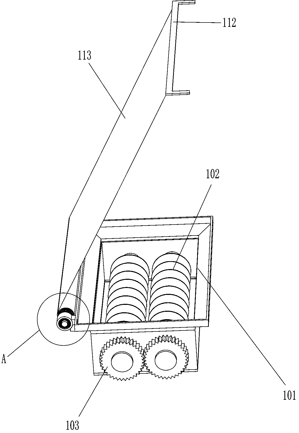
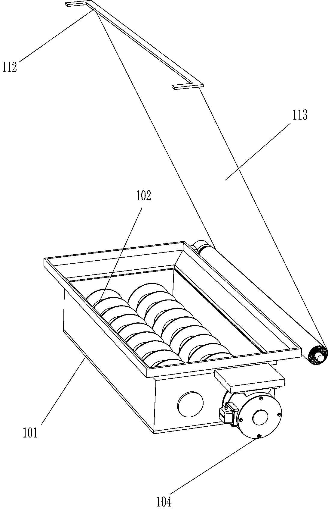
[0033] On the basis of Example 1, such as figure 1 , Figure 7 and Figure 9 As shown, it also includes a crushing mechanism 10. The crushing mechanism 10 includes a crushing frame 101, a crushing roller 102, a transmission gear 103 and a crushing motor 104. The left side and the right side of the base 1 are connected with crushing Material frame 101, the left and right sides of the front side of the crushed material frame 101 are all rotatably connected with connecting shafts, the rear end of the connecting shaft runs through the crushed material frame 101, and the connecting shaft in the crushed material frame 101 is connected with a crushed material roller 102. A transmission gear 103 is connected to the connecting shaft on the rear side of the material frame 101, and the two transmission gears 103 mesh, and a material motor 104 is installed on the front side of the material frame 101, and the output shaft of the material motor 104 is connected to the outside through a cou...


PUM


Abstract

The invention relates to waste removal equipment, in particular to die cutting waste removal equipment for a printshop. The technical problem to be solved is how to provide die cutting waste removal equipment for a printshop and capable of rapidly removing waste and reducing the labor intensity of workers. In order to solve the above technical problem, the die cutting waste removal equipment for the printshop is provided and comprises a base, sliding columns, removal mechanisms and a pressing mechanism. Rolling wheels are rotationally connected to the bottom of the base, and a handle holder isconnected to the top of the base. The position, close to the handle holder, of the top of the base is connected with the sliding columns, sliding frames are in sliding connection to the handle holder, a lifting frame is connected between one side faces of the sliding frames and is arranged on the sliding columns in a sleeving manner, and a pull rod is connected between the inner side faces of thesliding frames. The removal mechanisms are mounted on the lifting frame. The pressing mechanism is mounted at one ends of the sliding columns. Multiple removal wheels of the die cutting waste removalequipment rotate and move downwards, and waste sheets in various directions on paper shells obtained after die cutting can be cut.

Description

technical field [0001] The invention relates to a waste cleaning device, in particular to a die-cutting waste cleaning device for a printing factory. Background technique [0002] In order to conveniently make large pieces of paper shells into cartons, it is necessary to die-cut the paper shells, and then remove the waste pieces on the paper shells after die-cutting. At present, workers generally remove the waste pieces on the paper shells after die-cutting The removal method of tearing off, so the labor intensity of the workers is high, and the removal efficiency of waste pieces is low; in order to reduce the labor intensity and improve the removal efficiency, the workers will pile up the paper shells after die-cutting so that the paper shells after die-cutting can be piled up to a suitable size. Then the workers hold the electric cutting machine and move the electric cutting machine down to cut the waste pieces in one direction on the paper shell after die-cutting. After c...

Claims


Application Information

Patent Timeline
Patent Type & Authority Applications(China)
IPC IPC(8): B26D7/18B02C4/08B02C4/42B02C4/28B02C23/02B02C18/00B02C18/14B02C18/18B02C21/02B02C21/00B31B50/14B31B50/20B31B50/74
CPCB02C4/08B02C4/286B02C4/42B02C18/0084B02C18/14B02C18/182B02C21/00B02C21/02B02C23/02B02C2201/06B26D7/18B31B50/142B31B50/20B31B50/74
Inventor 万睿轩
Owner 赣州惠彩印刷有限公司
Why Eureka
Try Eureka