Calibration method, device, equipment and computer-readable storage medium of a coherent optical module

A technology of coherent light and coherent receiver, applied in the field of optical fiber

Active Publication Date: 2021-06-11
GUANGXUN SCI & TECH WUHAN
View PDF0 Cites 0 Cited by
  • Summary
  • Abstract
  • Description
  • Claims
  • Application Information

AI Technical Summary

Problems solved by technology

There is currently no effective solution to this problem

Method used


Image

  • Calibration method, device, equipment and computer-readable storage medium of a coherent optical module
  • Calibration method, device, equipment and computer-readable storage medium of a coherent optical module
  • Calibration method, device, equipment and computer-readable storage medium of a coherent optical module

Examples


Embodiment Construction

[0028] In order to make the purpose, technical solutions and advantages of the embodiments of the present invention more clear, the specific technical solutions of the invention will be further described in detail below in conjunction with the drawings in the embodiments of the present invention. The following examples are used to illustrate the present invention, but are not intended to limit the scope of the present invention.

[0029] The present invention will be described in further detail below in conjunction with the accompanying drawings and specific embodiments.

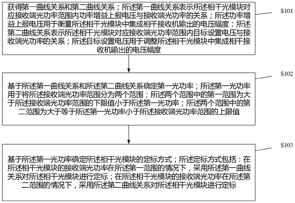
[0030] Such as figure 1 , which shows a schematic flow chart of a calibration method for a coherent optical module provided by an embodiment of the present invention. The method includes:

[0031] S101: Obtain a first curve relationship and a second curve relationship; the first curve relationship represents the relationship between the power gain reported voltage of the coherent optical module correspondi...


PUM


Abstract

The present invention discloses a calibration method, device, equipment, and computer-readable storage medium for a coherent optical module. The method includes: obtaining a first curve relationship and a second curve relationship; the first curve relationship indicates that the coherent optical module corresponds to a receiving end The relationship between the power gain reported voltage and the optical power of the receiving end within the optical power range; the second curve relationship represents the relationship between the coherent optical module corresponding to the target setting voltage within the optical power range of the receiving end and the optical power of the receiving end; based on the first curve relationship and the second The curve relationship determines the first optical power; the first optical power is used to divide the receiving end optical power range into two ranges; the calibration method of the coherent optical module is determined based on the first optical power; the calibration method includes: in the coherent optical module When the receiving end optical power is in the first range, use the first curve relationship to calibrate the coherent optical module; when the receiving end optical power of the coherent optical module is in the second range, use the second curve relationship to calibrate the coherent optical module The module is calibrated.

Description

technical field [0001] Embodiments of the present invention relate to the field of optical fiber technology, and in particular to a calibration method, device, equipment and computer-readable storage medium for a coherent optical module. Background technique [0002] For traditional coherent optical modules, the total optical power at the receiving end is generally reported by the receiving end photodiode (Photo Diode, PD) for calibration. For miniaturized modules, an external Tap Photo Detector (TAP-PD) cannot be accommodated. , may use the PD integrated in the receiver of the module for reporting and calibration. For module receiving receivers, some manufacturers may not integrate internal PDs. At this time, optical power calibration cannot rely on PDs. How to ensure the linearity of the reporting curve obtained in the entire optical power range of the receiving end without depending on the PD, and improve the reporting accuracy in the entire optical power range. For thi...

Claims


Application Information

Patent Timeline
Patent Type & Authority Patents(China)
IPC IPC(8): G06F17/15H04B10/61H04B10/564
CPCG06F17/15H04B10/616H04B10/564H04B10/61H04B10/806
Inventor 陈胜邹晖张武平
Owner GUANGXUN SCI & TECH WUHAN
Why Eureka
Try Eureka