
Received power reporting method of optical module and corresponding microprocessor

A receiving power and microprocessor technology, applied in electrical components, electromagnetic wave transmission systems, transmission systems, etc., can solve problems such as bit errors, receiver bit errors, and difficulty in ensuring reporting repeatability

Active Publication Date: 2021-03-19
SHANGHAI GONGJIN COMM TECH
View PDF3 Cites 0 Cited by
  • Summary
  • Abstract
  • Description
  • Claims
  • Application Information

AI Technical Summary

Problems solved by technology

If the power is too high, it will enter the saturation point and generate bit errors. If the power is too low, the receiver will also generate bit errors due to the influence of noise.
Limited by the cost, the hardware circuit can guarantee the reporting accuracy, because the reporting accuracy only needs to meet ±3dB, but it is difficult to guarantee the reporting repeatability, and customers often require the repeatability to meet ±0.5dB

Method used


Image

  • Received power reporting method of optical module and corresponding microprocessor

Examples


Embodiment Construction

[0014] In order to describe the technical content of the present invention more clearly, further description will be given below in conjunction with specific embodiments.

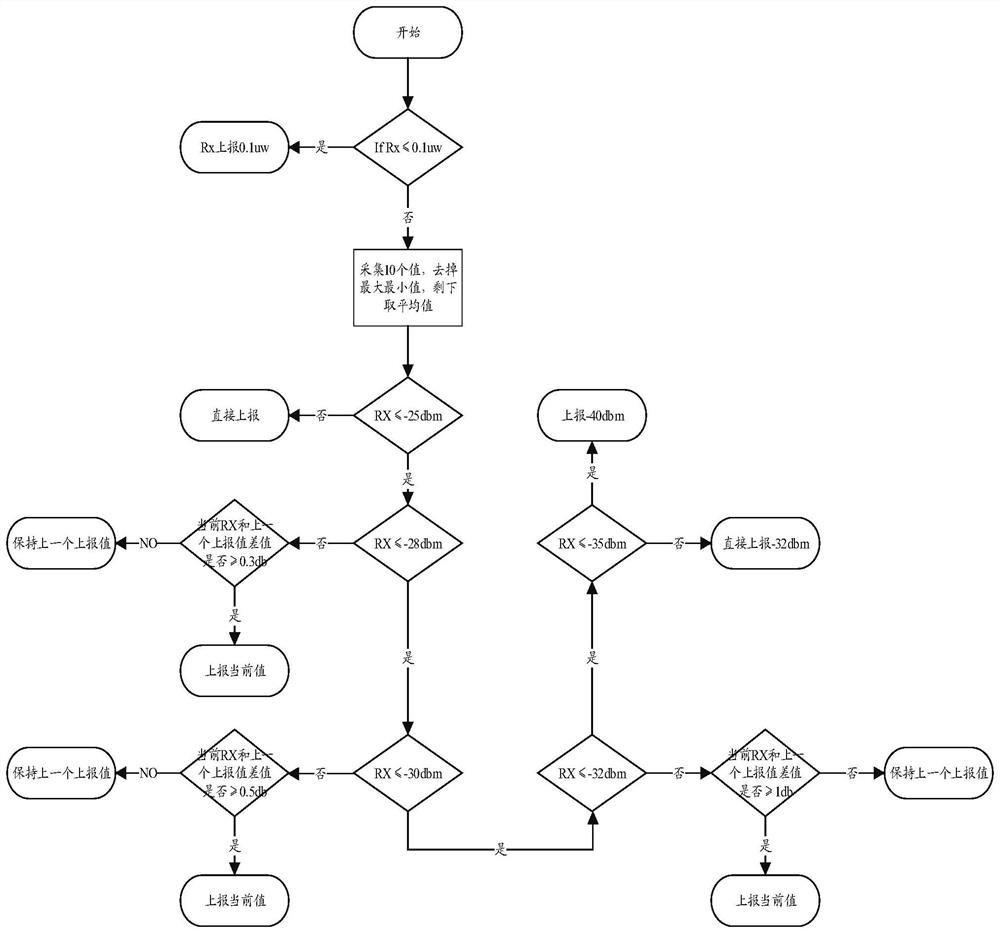
[0015] The receiving power reporting method of the optical module is: when the receiving power of the optical module is greater than the first threshold, then report the current real-time receiving power to the ONU; when the receiving power of the optical module is less than or equal to the fifth threshold, then report The fifth standard power to the ONU, and when the received power of the optical module is between the fifth threshold and the fourth threshold, report the fourth standard power to the ONU, otherwise, the current real-time received power and the previous report Calculate the power difference, and report correspondingly according to the magnitude of the obtained absolute value of the difference, the fifth threshold<the fourth threshold<the first threshold.

[0016] In the method for reporting t...


PUM


Abstract

The invention relates to a receiving power reporting method of an optical module. The method comprises the following steps: reporting the current real-time receiving power to an ONU, when the receiving power of the optical module is greater than a first threshold, reporting the fifth standard power to the ONU when the receiving power of the optical module is less than or equal to the fifth threshold, and reporting the fourth standard power to the ONU when the receiving power of the optical module is between the fifth threshold and the fourth threshold; or performing difference operation of thecurrent real-time receiving power and the previous reporting power, and correspondingly reporting according to the absolute value of the obtained difference. By adopting the receiving power reportingmethod of the optical module disclosed by the invention, the real-time reporting is adopted since the received optical power is stable when the optical power is strong; different reporting values areadopted through a setting interval when the optical power receiving is weak, so that the reporting precision is improved, and the reporting efficiency is improved.

Description

technical field [0001] The present invention relates to the field of communication technology, in particular to the field of communication technology of optical modules, and specifically refers to a method for reporting received power of an optical module and a corresponding microprocessor. Background technique [0002] In order to improve the stability and maintainability of the system, the optical module introduces the digital diagnosis system DDMI. The working voltage of the module, the bias current of the laser, the transmitting power of the laser, the receiving temperature of the module, and the temperature of the module can be detected through the auxiliary circuit. The module can only work normally under the appropriate received optical power. If the power is too high, it will enter the saturation point and generate bit errors. If the power is too low, the receiver will also generate bit errors due to the influence of noise. Limited by cost, the hardware circuit can...

Claims


Application Information

Patent Timeline
Patent Type & Authority Patents(China)
IPC IPC(8): H04B10/079
CPCH04B10/07955
Inventor 吕斌蒋昌明
Owner SHANGHAI GONGJIN COMM TECH
Learn More