Manipulator device convenient to adjust

A technology of manipulators and fixed frames, applied in the field of manipulators, can solve the problems of affecting parts grasping efficiency, inconvenient parts grasping, cumbersome manipulator operation, etc., to improve grasping efficiency and grasping effect, improve gripping effect, structure reasonable effect

Inactive Publication Date: 2020-11-03
熊祥
View PDF0 Cites 2 Cited by
  • Summary
  • Abstract
  • Description
  • Claims
  • Application Information

AI Technical Summary

Problems solved by technology

The rotation position of the existing manipulator device is fixed, and it is inconvenient to grasp the parts. The operation of the manipulator is cumbersome, and it is easy to cause damage to the surface of the parts, which is easy to affect the grasping efficiency of the parts

Method used


Image

  • Manipulator device convenient to adjust
  • Manipulator device convenient to adjust
  • Manipulator device convenient to adjust

Examples


Embodiment 1

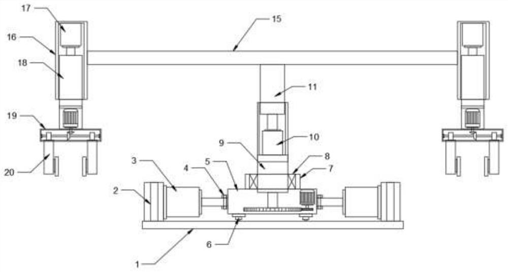
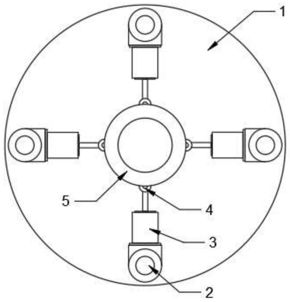
[0023] see Figure 1~4 , in the embodiment of the present invention, a manipulator device that is easy to adjust includes a base plate 1, a fixed frame 5 and a clamping plate 20, a first rotating shaft 2 is installed on the upper edge of the base plate 1, and a The first cylinder 3, the front end of the first cylinder 3 is provided with a fixed frame 5, the second rotating shaft 4 is installed between the first cylinder 3 and the fixed frame 5, the shapes of the base plate 1 and the fixed frame 5 are circular, and the first rotation Axis 2, the first cylinder 3 and the second rotating shaft 4 are all provided with four, which are divided into four groups and are evenly distributed on the outside of the fixed frame 5; Cylinder 7, the first rolling bearing 8 is installed on the inner side of the cylinder 7, the first supporting rod 9 is installed on the inner side of the first rolling bearing 8, the first gear 12 is installed on the bottom end of the first supporting rod 9, and ...

Embodiment 2

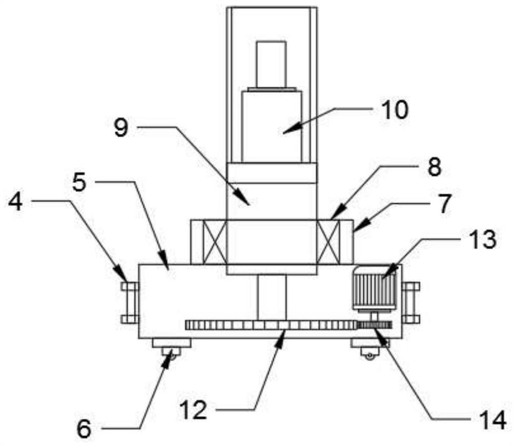
[0026] see Figure 5 , in the embodiment of the present invention, a manipulator device that is easy to adjust includes a base plate 1, a fixed frame 5 and a clamping plate 20, a first rotating shaft 2 is installed on the upper edge of the base plate 1, and a The first cylinder 3, the front end of the first cylinder 3 is provided with a fixed frame 5, the second rotating shaft 4 is installed between the first cylinder 3 and the fixed frame 5; A cylinder 7 is installed in the middle, a first rolling bearing 8 is installed inside the cylinder 7, a first support rod 9 is installed inside the first rolling bearing 8, a first gear 12 is installed at the bottom end of the first support rod 9, and the right end inside the fixed frame 5 The first motor 13 is installed, and the second gear 14 is installed on the front end of the first motor 13 shaft; The plate improves the stability of the connection between the first support bar 9 and the long bar 15 . Other structures in this embod...


PUM


Abstract

The invention discloses a manipulator device convenient to adjust. The manipulator device comprises a bottom plate, a fixing frame and a clamping plate, and a first rotating shaft, a first air cylinder, the fixing frame and a second rotating shaft are installed at the upper end of the bottom plate; a cylinder, a first rolling bearing and a first supporting rod are installed in the middle of the top end of the fixing frame, a first gear is installed at the bottom end of the first supporting rod, and a first motor and a second gear are installed at the right end of the inner side of the fixing frame; a second cylinder and a second supporting rod are mounted on the inner side of the upper end of the first supporting rod, and a long rod is mounted at the top end of the second supporting rod; and limiting frames are installed at the two ends of a long rod, third air cylinders and connecting rods are installed at the top ends of the inner sides of the limiting frames, supporting frames are installed at the bottom ends of the connecting rods, threaded rods are installed in the middles of the inner sides of the supporting frames, second bevel gears are installed in the middles of the threaded rods, second motors and first bevel gears are installed on the inner sides of the bottom ends of the connecting rods, and sliding blocks and clamping plates are installed on the outer sides of thethreaded rods. The manipulator device is reasonable in structure and convenient to adjust, and the grabbing efficiency and the grabbing effect are improved.

Description

technical field [0001] The invention relates to the technical field of manipulators, in particular to a manipulator device that is easy to adjust. Background technique [0002] The manipulator is a kind of production equipment that is often used in manufacturing. The manipulator can improve production efficiency and reduce the work intensity of laborers. There are all kinds of mechanical arms in the prior art, and the mechanical arm capable of turning is a common mechanical arm in the prior art. This mechanical arm has a relatively large working range and can rotate around the rotating connecting column, but in some cases Next, we need to make the rotation center of the rotary robot arm adjustable within a certain range to meet the needs of manufacturing. In production, it is often necessary to use a manipulator to grab parts with low hardness and perform centering installation. When grabbing parts, no traces can be pressed on the surface of the parts. When installing the p...

Claims


Application Information

Patent Timeline
IPC IPC(8): B25J9/04B25J9/10B25J15/00
CPCB25J9/04B25J9/1005B25J9/102B25J15/0057
Inventor 熊祥
Owner 熊祥
Why Eureka
Try Eureka