Electric automatic clamp

A technology of electrical automation and fixtures, applied in the direction of clamping, manufacturing tools, supports, etc., can solve the problems of poor positioning effect, unstable clamping effect, inconvenient adjustment of the positioning diameter of the fixture, etc., to achieve smooth contact surface and clamping effect Good, high control precision effect

Active Publication Date: 2020-07-10
韦尔德海润(北京)智能科技有限公司
View PDF7 Cites 1 Cited by
  • Summary
  • Abstract
  • Description
  • Claims
  • Application Information

AI Technical Summary

Problems solved by technology

[0004] Aiming at the deficiencies of the prior art, the present invention provides an electrical automation fixture, which solves the problem that the clamping effect of the existing pipeline steel bar clamp is not stable enough, it is inconvenient to adjust the positioning diameter of the clamp, and the positioning effect is poor

Method used


Image

  • Electric automatic clamp
  • Electric automatic clamp
  • Electric automatic clamp

Examples


Embodiment Construction

[0026] The following will clearly and completely describe the technical solutions in the embodiments of the present invention with reference to the accompanying drawings in the embodiments of the present invention. Obviously, the described embodiments are only some, not all, embodiments of the present invention. Based on the embodiments of the present invention, all other embodiments obtained by persons of ordinary skill in the art without making creative efforts belong to the protection scope of the present invention.

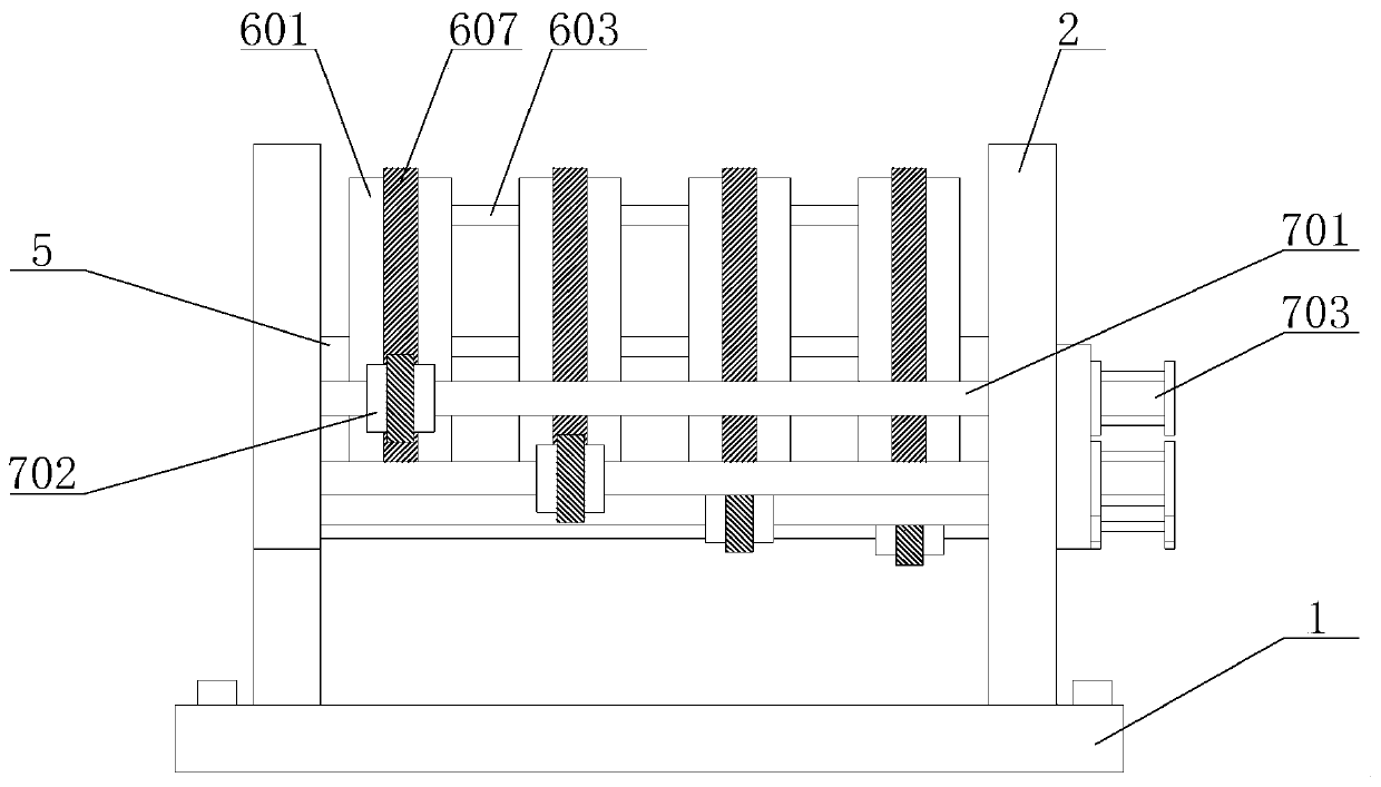
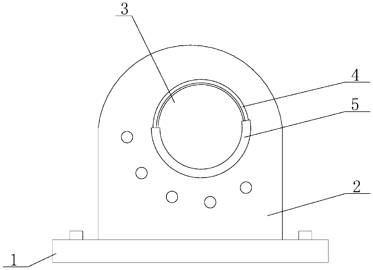
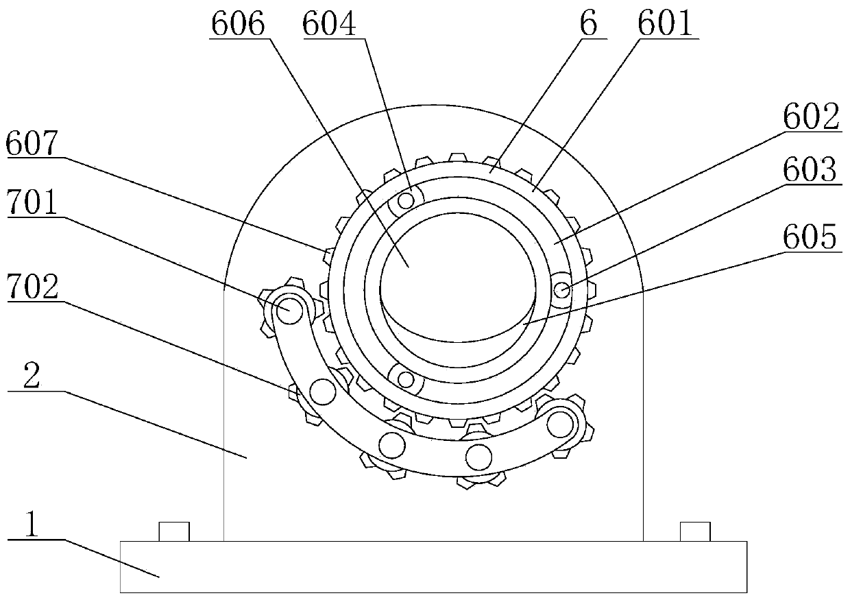
[0027] see Figure 1-3 , an electrical automation fixture, comprising a base 1, the left and right sides of the top surface of the base 1 are fixedly connected with support plates 2, and the opposite sides of the two support plates 2 are provided with opposite through holes 3 and connecting ring grooves 4, The cross section of the connecting ring groove 4 is L-shaped, and a slider 5 is slidably connected to the inner side of the ring groove.

[0028] Four pos...


PUM


Abstract

The invention discloses an electric automatic clamp, and relates to the field of electrical automation equipment. The electric automatic clamp comprises a base, supporting plates are fixedly connectedto the left side and the right side of the top face of the base, through holes and connecting annular grooves which are opposite in positions are formed in the opposite sides of the two supporting plates, and the cross sections of the connecting annular grooves are in an L shape. According to the electric automatic clamp, the overlapping area of vertical plane mapping of the electric automatic clamp is reduced through the rotation of positioning rings by utilizing the mutual dislocation effect among four convex blocks, so that the clamping effect on column hard part structures such as pipelines and reinforcing steel bars which penetrate the axial lead direction of the positioning rings is realized, gear motors are used for driving control rods to rotate to achieve rotation control over the four positioning rings, automatic mechanical control management is achieved, the control precision is higher, the clamping effect on a column hard part is better and more stable in cooperation withthe curved surface effect of the convex blocks, and the problems that an existing pipeline steel bar clamp is not stable enough in clamping effect, the positioning diameter of the clamp is inconvenient to adjust, and the positioning effect is poorer are solved.

Description

technical field [0001] The invention relates to the field of electrical automation equipment, in particular to an electrical automation fixture. Background technique [0002] With the continuous improvement of the intelligence of modern lathes, the shapes of modern mechanical equipment are becoming more and more diverse. Tubular and cylindrical mechanical parts, as parts with conventional shapes, need to use fixtures to fix their positions during processing and maintenance before they can be processed. [0003] Existing patent (notification number: CN107971772A) discloses a kind of copper pipe fixture; Through the base, the support is set on the base; The support is provided with a rotating shaft, and one end of the rotating shaft is provided with a handle. In the process of realizing the solution, the inventor found that the following problems in the prior art have not been solved: 1. Using the support shaft to clamp and maintain the mechanical parts of tubular or columnar...

Claims


Application Information

Patent Timeline
Patent Type & Authority Applications(China)
IPC IPC(8): B23Q3/06
CPCB23Q3/064
Inventor 杨秀鹏
Owner 韦尔德海润(北京)智能科技有限公司
Why Eureka
Try Eureka