Recuperator tube device used for boiler

A technology for heat exchange tubes and boilers, which is applied in the direction of boiler water tubes, etc., and can solve the problems of easy falling off of the refractory material layer and different thermal expansion coefficients.

Inactive Publication Date: 2008-01-02
宫树同
View PDF0 Cites 1 Cited by
  • Summary
  • Abstract
  • Description
  • Claims
  • Application Information

AI Technical Summary

Problems solved by technology

[0003] The technical problem to be solved by the present invention is to provide a heat exchange tube device for boilers to solve the problem that the refractory mate

Method used


Image

  • Recuperator tube device used for boiler

Examples


Embodiment Construction

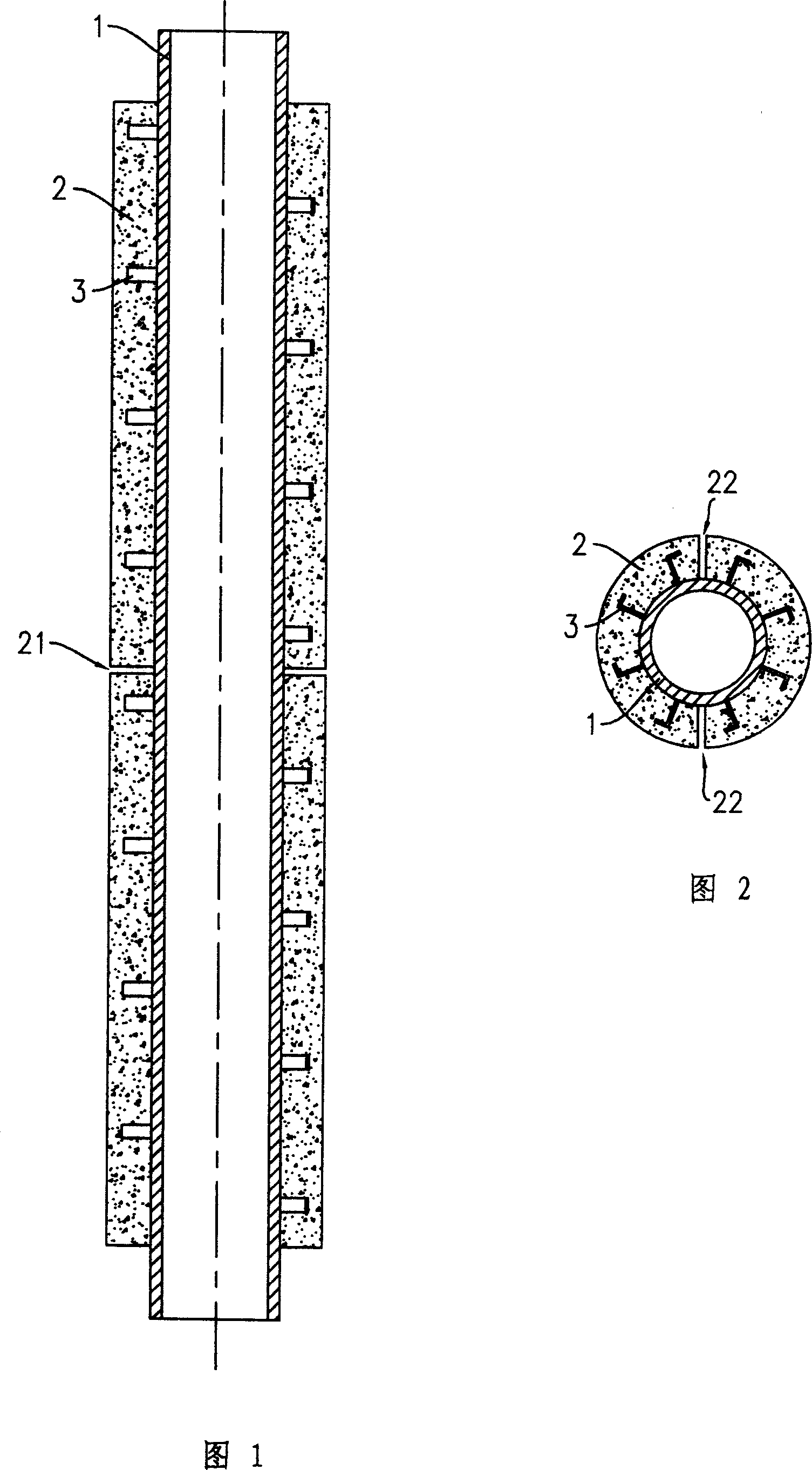
[0012] The heat exchange tube device for a boiler, as shown in Figure 1 and Figure 2, includes a heat exchange tube body 1, and a refractory material layer 2 coated on the heat exchange tube body 1, and the heat exchange tube body 1 is made of metal material, and the refractory material layer 2 is made of refractory material. The root of the fixing claw 3 is fixed on the outer surface of the heat exchange tube body 1. After the refractory material is cast on the outer peripheral surface of the heat exchange tube body 1, the fixing claw 3 can make the refractory material layer 2 firmly adhere to the heat exchange tube ontology. According to needs, many fixing claws 3 can be provided, and these fixing claws 3 are arrayed in the circumferential direction of the heat exchange tube body 1, and the fixing claws 3 between two adjacent ring array groups are arranged in a staggered manner, so that the distribution is more precise. Uniform, better grip. For the sake of simplicity, the...


PUM


Abstract

The invention discloses a heat transfer pipe device for boiler, which is characterized by the following: comprising heat transfer pipe body, fireproof material layer and solid jaw; coating the fireproof material layer on the heat transfer pipe body; adhering the fireproof material layer to the heat transfer pipe body with the solid jaw; fixing the roots of the solid jaw to the outer surface of the heat transfer pipe body; arranging ring form seam on the fireproof material layer to receive longitudinal dilatation quantity and longitudinal straight joint to receive longitudinal dilatation quantity. This invention possesses good high-temperature behavior resistance and long durability, which can be used to various boiler.

Description

technical field [0001] The invention relates to the technical field of heat exchange tube devices, in particular to a heat exchange tube device for boilers. Background technique [0002] In boilers heated by coal, etc., many heat exchange tubes are installed, and the outside is generally in direct contact with pyrotechnics, flue gas, or other high-temperature media, while the inner cavity of the heat exchange tube is the channel for heat exchange media such as air, water, and heat transfer oil. , the heat exchange medium realizes heat exchange in the heat exchange tube. In order to improve the high temperature resistance of the heat exchange tube, its outer peripheral surface is usually coated with a refractory layer made of refractory material. However, during use, due to the difference in thermal expansion coefficient between the heat exchange tube body and the refractory layer, the refractory layer is easy to fall off when subjected to temperature changes of heating-expa...

Claims


Application Information

Patent Timeline
IPC IPC(8): F22B37/10
Inventor 宫树同
Owner 宫树同
Why Eureka
Try Eureka