Flue gas dehumidification system

A flue gas and flue gas heat exchanger technology, applied in the field of flue gas dehumidification system, can solve the problems of unsatisfactory flue gas dehumidification effect and low efficiency, and achieve the effect of improving dehumidification effect, efficiency and dehumidification effect

Pending Publication Date: 2020-11-10
HANDAN COLLEGE
View PDF8 Cites 0 Cited by
  • Summary
  • Abstract
  • Description
  • Claims
  • Application Information

AI Technical Summary

Problems solved by technology

[0004] In view of this, the embodiment of the present invention provides a flue gas dehumidification system to solve the problems of low efficiency and unsatisfactory flue gas dehumidification effect in most of the existing technologies

Method used


Image

  • Flue gas dehumidification system
  • Flue gas dehumidification system
  • Flue gas dehumidification system

Examples


Embodiment Construction

[0034] In the following description, specific details such as specific system structures and technologies are presented for the purpose of illustration rather than limitation, so as to thoroughly understand the embodiments of the present application. It will be apparent, however, to one skilled in the art that the present application may be practiced in other embodiments without these specific details. In other instances, detailed descriptions of well-known systems, devices, circuits, and methods are omitted so as not to obscure the description of the present application with unnecessary detail.

[0035] In order to illustrate the technical solutions of the present invention, specific examples are used below to illustrate.

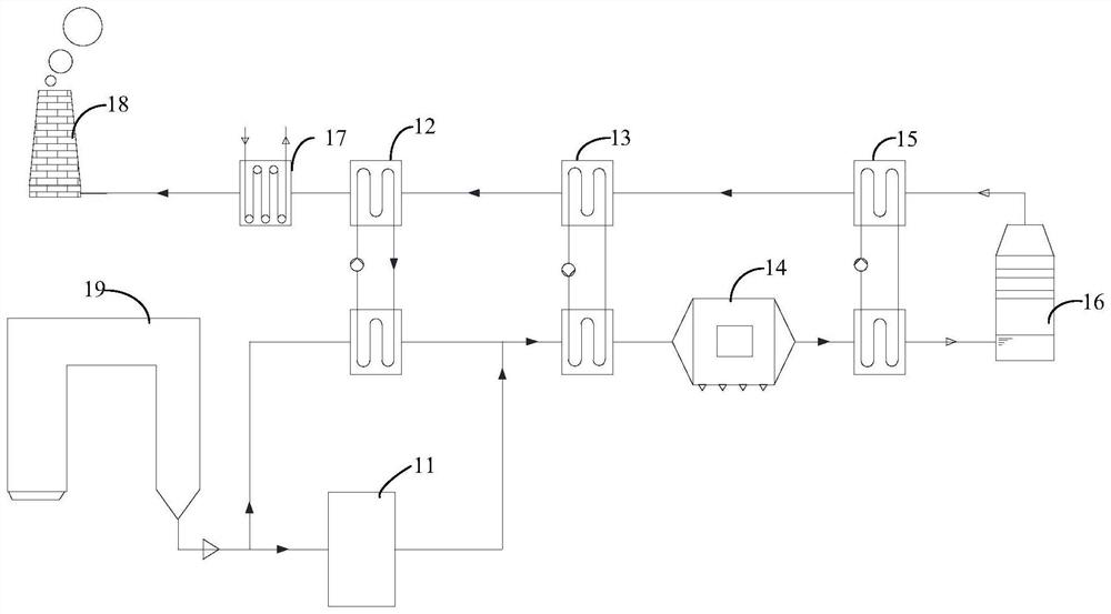
[0036] figure 1 It is a schematic structural diagram of a flue gas dehumidification system provided by an embodiment of the present invention. For convenience of description, only the parts related to the embodiment of the present invention are shown. li...


PUM


Abstract

The converged flue gas sequentially passes through the rotary flue gas heat exchanger, the dust remover, the low-temperature water medium type flue gas heat exchanger and the desulfurizing tower to obtain desulfurized flue gas; and the desulfurized flue gas sequentially passes through the low-temperature water medium type flue gas heat exchanger, the rotary type flue gas heat exchanger, the high-temperature water medium type flue gas heat exchanger and the composite type flue gas heater to be conveyed to an external chimney. According to the flue gas dehumidification system, full gradient utilization of flue gas waste heat can be achieved, the efficiency can be improved, and the flue gas dehumidification effect of a unit can be improved. The invention belongs to the technical field of environmental protection, and discloses a flue gas dehumidification system. The flue gas dehumidification system comprises an air preheater, a high-temperature water medium type flue gas heat exchanger, arotary flue gas heat exchanger, a dust remover, a low-temperature water medium type flue gas heat exchanger, a desulfurizing tower and a composite flue gas heater; boiler flue gas comprises main fluegas and bypass flue gas, and the main flue gas passes through the air preheater and then is converged with the bypass flue gas passing through the high-temperature water medium type flue gas heat exchanger to obtain converged flue gas;.

Description

technical field [0001] The invention belongs to the technical field of environmental protection, and in particular relates to a flue gas dehumidification system. Background technique [0002] When wet desulfurization is used for flue gas desulfurization, the flue gas temperature at the desulfurization outlet is about 50°C. At this time, the flue gas is usually in a state of saturated humidity, and the saturated humidity flue gas is rapidly cooled by the lower temperature atmosphere after being discharged from the chimney. The water vapor in the flue gas condenses into a liquid state, and the light transmittance decreases, resulting in the phenomenon of white wet plume visible to the naked eye; as the water vapor diffuses in the atmosphere, the concentration of water vapor decreases, the light transmittance increases, and the white wet smoke plume appears. The plumage slowly decreases until it disappears from view. [0003] There are many methods for flue gas dehumidificatio...

Claims


Application Information

Patent Timeline
Patent Type & Authority Applications(China)
IPC IPC(8): F23J15/06F23J15/02F23J15/00G06N3/00
CPCF23J15/06F23J15/022F23J15/006G06N3/006Y02E20/30
Inventor 程亮
Owner HANDAN COLLEGE
Why Eureka
Try Eureka