Photographic device

A photographic device and base technology, which is applied to photographic filters, cameras, instruments, etc., can solve problems such as distortion and unclear images, and achieve the effect of avoiding rising production costs and reducing stray light

Inactive Publication Date: 2020-11-20
LUXVISIONS INNOVATION LTD
View PDF15 Cites 0 Cited by
  • Summary
  • Abstract
  • Description
  • Claims
  • Application Information

AI Technical Summary

Problems solved by technology

The reflected light can be called as stray light (flare), and these stray light will also be sensed by the sensing unit and become part of the image, thus causing the image to be unclear or distorted

Method used


Image

  • Photographic device
  • Photographic device
  • Photographic device

Examples


Embodiment Construction

[0041] Below in conjunction with accompanying drawing, structural principle and working principle of the present invention are specifically described:

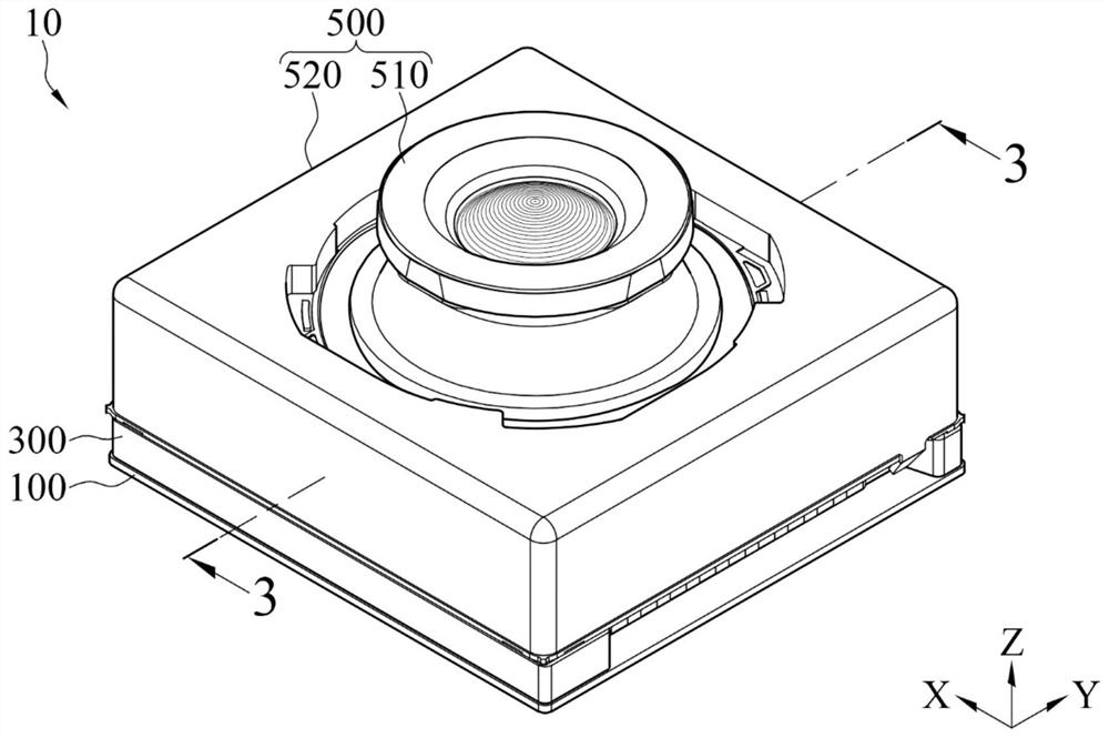
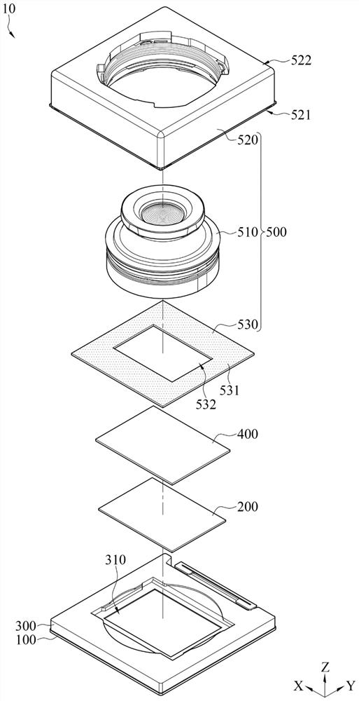
[0042] Please refer to figure 1 and figure 2 , figure 1 Shown is a schematic diagram of an imaging device 10 according to an embodiment of the present invention, figure 2 Shown is an exploded view of a camera device 10 according to an embodiment of the present invention. In this embodiment, the camera device 10 is used in portable electronic devices, such as smart phones or tablet computers, but is not limited thereto. The photographic device 10 includes a bottom plate 100 , a sensing unit 200 , a base 300 , a filter 400 and a lens module 500 . The sensing unit 200 is located on the bottom board 100 . The base 300 is located on the bottom plate 100 and surrounds the sensing unit 200 , and the base 300 includes an opening 310 . The filter 400 is located on the base 300 and covers the opening 310 . The lens module 500 i...


PUM


Abstract

A photographic device comprises a bottom plate, a sensing unit, a base, an optical filter and a lens module. The sensing unit is located on the bottom plate, and the base is located on the bottom plate and surrounds the sensing unit. The base comprises an opening, and the optical filter is located on the base and covers the opening. The lens module comprises a lens barrel, a lens mount and a lightshielding plate, the lens barrel is located in the lens mount, the lens mount is connected with the base, the light shielding plate comprises a light shielding part and a light transmitting opening,the light shielding part surrounds the light transmitting opening, and the lens barrel, the light transmitting opening, the opening and the sensing unit are aligned with one another in the light incident direction. Through the design of the light shielding plate, stray light can be effectively reduced, and the production cost can be prevented from rising.

Description

technical field [0001] The present invention relates to a photographic device, and in particular to a photographic device for a portable electronic device. Background technique [0002] Many of today's portable electronic devices, such as smart phones or tablet computers, have photography functions. This photography device is composed of a lens, a filter, a sensing unit and a bracket. The lens, filter and sensing unit Aligned and fixed in the bracket, the optical filter is located between the lens and the sensing unit, and the bracket is fixed at a specific position of the portable electronic device. The external light will be projected on the sensing unit after passing through the lens and the filter, so that the sensing unit can sense the light and generate an image. Generally speaking, the light will first enter through the lens, then pass through the lens, and finally project to the sensing area on the sensing unit, but the projected light from the lens will not be comp...

Claims


Application Information

Patent Timeline
Patent Type & Authority Applications(China)
IPC IPC(8): G03B11/04
CPCG03B11/04
Inventor 张耀中曾正德张宗凯
Owner LUXVISIONS INNOVATION LTD
Why Eureka
Try Eureka