

Rotary clamp device
A technology of rotating fixture and rotating mechanism, applied in positioning devices, clamping, manufacturing tools, etc., can solve the problems of reducing production efficiency, not applicable to modern production requirements of small batches and multiple varieties, and increasing production costs.
- Summary
- Abstract
- Description
- Claims
- Application Information
AI Technical Summary
Problems solved by technology
Method used
Image

Examples
Embodiment Construction
[0015] In order to enable those skilled in the art to better understand the technical solution of the present invention, the application will be described in detail below in conjunction with the accompanying drawings. The description in this part is only exemplary and explanatory, and should not have any limiting effect on the protection scope of the application. .
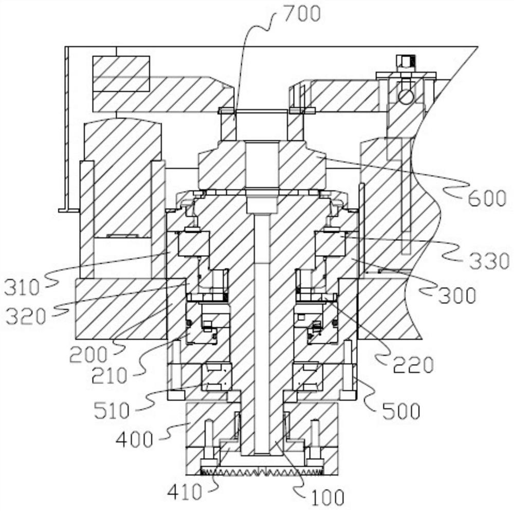
[0016] Such as figure 1 Shown is a schematic diagram of the first embodiment of the present application, including a central shaft 100 and set up on the outside of the central shaft 100 from bottom to top: a rotating mechanism, a jacking mechanism, and a fixed support mechanism; the rotating mechanism snaps At the bottom end of the central shaft 100; the jacking mechanism includes a cylinder body 200, and the inside of the cylinder body 200 is provided with a vertically telescopic locking piston 210, and the fixed support mechanism includes a support 300, and the support 300 The lower edge of the corresponding lo...
PUM
 Abstract
Description
Claims
Application Information