Biomass particle furnace

A technology of biomass particles and furnace body, which is applied in the direction of combustion method, block/powder supply/distribution, indirect carbon dioxide emission reduction, etc., which can solve the waste of electricity in ignition devices, poor heat exchange effect, and low market share, etc. problems, to achieve the effect of reducing waste, sufficient heat exchange, and sufficient heat

Inactive Publication Date: 2021-01-01
廖代云
View PDF0 Cites 0 Cited by
  • Summary
  • Abstract
  • Description
  • Claims
  • Application Information

AI Technical Summary

Problems solved by technology

[0005] The invention provides a biomass pellet stove, which has the advantages of more sufficient heat exchange for the hot gas generated by combustion, the size of the flame is controlled by the amount of oxygen, and after the heat preservation is extinguished, the biomass pellets can spontaneously ignite for combustion and heating, increasing the cooling function in summer It solves the problem that the heat exchange effect of the combustion is poor, and the biomass particles are extinguished after heat preservation, and the ignition device needs to be restarted to waste electricity for re-combustion, and the existing equipment is not available in summer, which leads to the inability to fully promote and low market share.

Method used


Image

  • Biomass particle furnace
  • Biomass particle furnace
  • Biomass particle furnace

Examples


Embodiment Construction

[0022] The following will clearly and completely describe the technical solutions in the embodiments of the present invention with reference to the accompanying drawings in the embodiments of the present invention. Obviously, the described embodiments are only some, not all, embodiments of the present invention. Based on the embodiments of the present invention, all other embodiments obtained by persons of ordinary skill in the art without making creative efforts belong to the protection scope of the present invention.

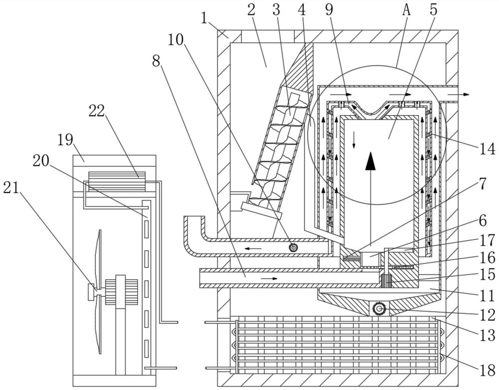
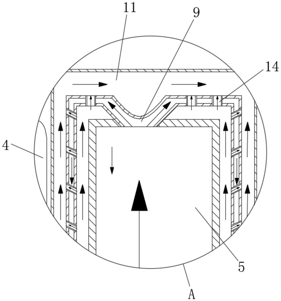
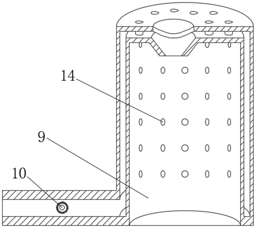
[0023] see Figure 1-5 , a biomass pellet furnace, including a furnace body 1, a material box 2 is separated on one side of the upper part of the inner cavity of the furnace body 1, and an auger 3 is fixedly installed on one side of the upper part of the inner cavity of the furnace body 1 and matched with the material box 2 One side of the upper part of the auger 3 is connected with a material pipe 4, and one side of the inner cavity of the furnace body 1 is f...


PUM


Abstract

The invention relates to the technical field of household equipment, and discloses a biomass particle furnace. The biomass particle furnace comprises a furnace body, a material box is separated on oneside of the upper portion of an inner cavity of the furnace body, a spiral screw is fixedly installed on one side of the upper portion of the inner cavity of the furnace body and installed to the material box in a matching mode, a material pipe communicates with one side of the upper portion of the spiral screw, and an air sleeve is fixedly installed on one side of an inner cavity of the furnacebody. According to the biomass particle furnace, through mutual sleeving of a combustion chamber, a heat exchange sleeve and the air sleeve, hot gas passes through the heat exchange sleeve after biomass particles in the combustion chamber are combusted, indoor air flows through the two sides of the heat exchange sleeve, the heat exchange area is large, more heat is absorbed by the hot gas flowingin the heat exchange sleeve, meanwhile, a ventilation pipe can guarantee that the indoor air on the inner surface of the heat exchange sleeve flow to the outer surface of the heat exchange sleeve, when the indoor air passes through the ventilation pipe, due to the fact that the hot gas directly impacts the ventilation pipe, the heat of the ventilation pipe is sufficient, heat exchange is more sufficient, and it is guaranteed that the heat generated by biomass particle combustion can be further utilized.

Description

technical field [0001] The invention relates to the technical field of household equipment, in particular to a biomass pellet stove. Background technique [0002] Biomass pellet stove is heating equipment in winter. Unlike traditional fireplaces, traditional stoves use wood, coal, and gas for heating, while biomass pellet fireplaces use biomass pellet energy fuel. It is a kind of The processed new energy fuel has higher combustion heat, full combustion, and cheaper use cost than traditional equipment. Biomass pellet fuel is a renewable resource, does not contain sulfur and phosphorus, and does not produce sulfur dioxide and phosphorus pentoxide when burned. It will lead to acid rain and air pollution. The carbon dioxide emitted during the combustion of biomass is as much as that absorbed in photosynthesis during the growth process. Therefore, from the perspective of recycling, the net emission of carbon dioxide to the air by biomass fuel is zero. . [0003] Biomass pellet ...

Claims


Application Information

Patent Timeline
Patent Type & Authority Applications(China)
IPC IPC(8): F23B40/00F23K3/16F23L15/04
CPCF23B40/00F23K3/16F23L15/04Y02E20/34
Inventor 廖代云
Owner 廖代云
Why Eureka
Try Eureka