Cable trench structure beneficial to slowing down cable corrosion

A cable corrosion and cable trench technology, applied in the field of cable trench structure, can solve problems such as cable corrosion, and achieve the effects of alleviating corrosion, avoiding the decline of dehumidification ability and reducing humidity

Active Publication Date: 2021-01-01
ZIYANG POWER SUPPLY COMPANY STATE GRID SICHUAN ELECTRIC POWER
View PDF8 Cites 0 Cited by
  • Summary
  • Abstract
  • Description
  • Claims
  • Application Information

AI Technical Summary

Problems solved by technology

[0006] The purpose of the present invention is to provide a cable trench structure that is conducive to slowing down the cable corrosion, so as to solve the problem that the existing cable trench is easy to aggravate the cable corrosion in a humid environment

Method used


Image

  • Cable trench structure beneficial to slowing down cable corrosion
  • Cable trench structure beneficial to slowing down cable corrosion

Examples


Embodiment 1

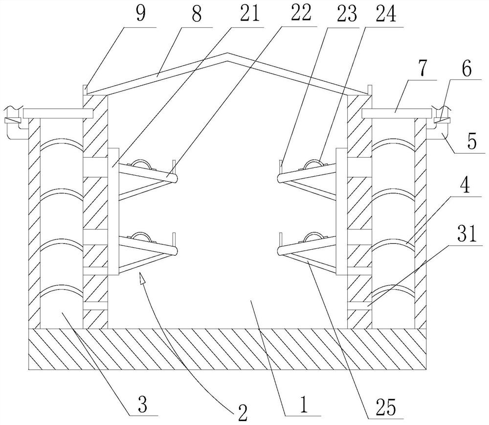
[0044]Such asfigure 1 ,figure 2As shown, the cable trench structure that is beneficial to alleviate cable corrosion includes a trench 1, the top of the trench 1 is matched with a top cover 8, the inner wall of the trench 1 is provided with a cable support 2, and the cable support 2 includes The fixing plate 21 is connected to the inner wall of the channel 1 by bolts, the fixing plate 21 is provided with a supporting plate 22, the side wall of the channel 1 is provided with an interlayer 3, and the inner side of the interlayer 3 The wall is provided with a number of ventilation holes 31 for connecting the channel 1 and the interlayer 3. A plurality of drying plates 4 are arranged in the interlayer 3, and the drying plate 4 is filled with desiccant, and the drying plate 4 is convex upward The desiccant is in a bag structure. The desiccant is made of a ventilated fabric. The desiccant is put into the bag, and then the bag is spread on the drying plate 4, which includes a bottom plate a...

Embodiment 2

[0046]Such asfigure 1 ,figure 2As shown, this embodiment is based on Embodiment 1. The interlayer 3 is provided with a number of first humidity sensors, the channel 1 is provided with a number of second humidity sensors, and also includes a ventilation duct 5 communicating with the interlayer 3. A fan 6 is provided on the ventilation duct 5, and the fan 6 is used to guide the airflow in the interlayer 3, and further includes a controller;

[0047]The first humidity sensor and the second humidity sensor are respectively used to sense the humidity inside the interlayer 3 and the channel 1 in real time, and transmit the sensed humidity signal to the controller;

[0048]The controller receives the humidity signal and makes an analysis to determine whether to turn on the fan 6;

[0049]After the fan 6 receives an instruction from the controller, it automatically turns on and derives the airflow in the mezzanine 3;

[0050]It also includes a terminal, which is connected to the controller in communica...

Embodiment 3

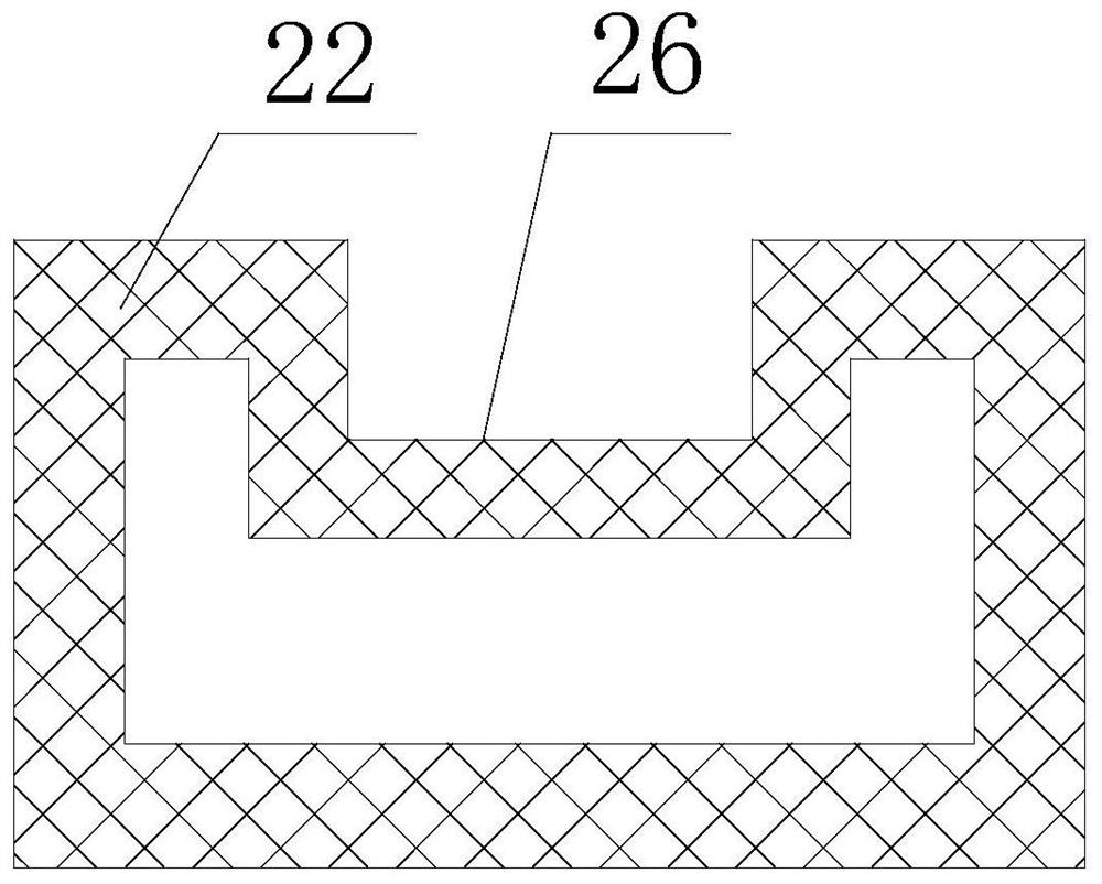
[0052]Such asfigure 1 ,figure 2As shown, this embodiment is based on Embodiment 1, the supporting plate 22 is arranged obliquely, the high end of the supporting plate 22 is the end connected to the fixing plate 21, and the lower end of the supporting plate 22 is provided with a baffle 23, so The supporting plate 22 is a hollow structure, a number of through holes are provided on the side wall of the supporting plate 22, and the fixing plate 21 is provided with communicating holes for communicating the supporting plate 22 with the ventilation holes 31; the supporting plate 22 is A square structure, the upper end of the square structure is recessed downward to form a groove 26, and the bottom of the baffle 23 is fixed at the lower end of the groove 26; a reinforcing plate is provided between the bottom of the supporting plate 22 and the fixing plate 21 25.


PUM


Abstract

The invention discloses a cable trench structure beneficial to slowing down cable corrosion. The structure comprises a trench, a top cover is arranged at the top of the trench in a matched mode, a cable support is arranged on the inner wall of the trench, an interlayer is arranged on the side wall of the trench, and a plurality of vent holes used for communicating the trench with the interlayer are formed in the inner side wall of the interlayer. A plurality of drying plates are arranged in the interlayer and filled with drying agents. The interlayer is arranged on the side wall of the channel, the drying agent is arranged in the interlayer, meanwhile, the vent holes are formed in the inner side channel wall, damp airflow in the channel is guided into the interlayer through the vent holes,the humidity in the channel is reduced, cable corrosion can be relieved, and the problem that cable corrosion of an existing cable channel is likely to be aggravated in the damp environment is solved.

Description

Technical field[0001]The invention relates to the technical field of power facilities, in particular to a cable trench structure that is beneficial to slow down cable corrosion.Background technique[0002]Cable trenches are underground pipes used to lay and replace power or telecommunications cable facilities, as well as the enclosure structure of the cable facilities to be laid. There are rectangular, circular, and arched pipe structures.[0003]The cable trench is a trench with a cover, and a cable support is installed in the cable trench. The cable support is usually made of metal materials and fixed on the trench wall by welding or using screws. The cable is supported by the bracket and kept a certain distance from the bottom of the trench; the cable in the cable trench is usually fireproofed, including painting fireproof paint, blocking and isolating.[0004]Depending on the number of cables to be laid, the cables can be placed in a single layer at the bottom of the cable trench, or ...

Claims


Application Information

Patent Timeline
IPC IPC(8): H02G9/02B01D53/26
CPCH02G9/02B01D53/26
Inventor 向子全陈斌李德伟魏琴刘洋
Owner ZIYANG POWER SUPPLY COMPANY STATE GRID SICHUAN ELECTRIC POWER
Why Eureka
Try Eureka