Corrosion prevention arrangement structure and method of heating surface of waste incineration boiler

A technology of waste incineration and layout structure, which is applied in the combustion method, incinerator, combustion type, etc., can solve the problems of poor surface flatness, large consumption of nickel-based alloys, and high cost of anti-corrosion layer layout, and achieves accelerated work. The effect of quality circulation, improving anti-corrosion performance, economical and effective anti-corrosion performance

Active Publication Date: 2021-08-13
SHANGHAI SUS ENVIRONMENT
View PDF12 Cites 0 Cited by
  • Summary
  • Abstract
  • Description
  • Claims
  • Application Information

AI Technical Summary

Problems solved by technology

[0003]Currently, the nickel-based alloy anti-corrosion coating on the heating surface of high-parameter boilers is all surfacing, and there are problems such as large consumption of nickel-based alloys and poor surface smoothness. Not only does it lead to the high cost of the layout of the anti-corrosion layer, but the anti-corrosion effect is also unsatisfactory.

Method used


Image

  • Corrosion prevention arrangement structure and method of heating surface of waste incineration boiler
  • Corrosion prevention arrangement structure and method of heating surface of waste incineration boiler
  • Corrosion prevention arrangement structure and method of heating surface of waste incineration boiler

Examples


Embodiment 1

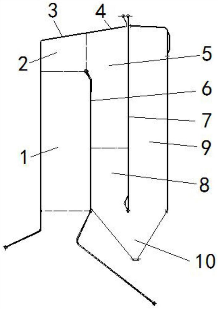
[0049] This embodiment provides an anti-corrosion layout structure of the heating surface of the waste incineration boiler, the structure of the boiler flue is as follows figure 1 As shown, it includes a flue, a second flue and a third flue arranged in sequence along the flue gas flow direction, the flue gas flows from bottom to top along the first flue, and flows from top to bottom along the second flue, It flows from bottom to top along the three flues, and the bottom of the second flue and the third flue communicate with the ash hopper (10); the anti-corrosion layout structure of the heating surface of the boiler is specifically as follows:

[0050] A refractory pouring anticorrosion layer is arranged on the heating surface of the lower part (1) of the flue;

[0051] The heating surface of the upper part of the first flue (2) and the heating surface of the side wall of the second flue (5) where the smoke temperature is higher than 750°C are arranged with a surfacing anti-co...

Embodiment 2

[0057] The surfacing, laser cladding and micro-fusion welding techniques implemented in Example 1 are compared and analyzed, and the results are shown in Table 1:

[0058] Table 1 Comparison of three anti-corrosion coating technologies

[0059]

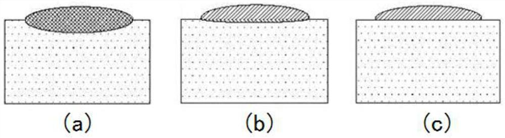
[0060] When surfacing welding, laser cladding and micro-fusion welding technologies are used to arrange the anti-corrosion layer, its penetration on the base material is as follows: figure 2 as shown, figure 2 It is a schematic diagram of the structure of the anti-corrosion layer formed by surfacing, laser cladding and micro-fusion welding provided by the embodiment of the present invention, wherein (a) is surfacing welding, (b) is laser cladding, and (c) is micro-fusion welding form. It can be seen that the penetration depth of the alloy layer in the form of surfacing welding is the largest, the penetration depth of the alloy layer in the form of micro-fusion welding is the smallest, and the penetration depth of the alloy laye...

Embodiment 3

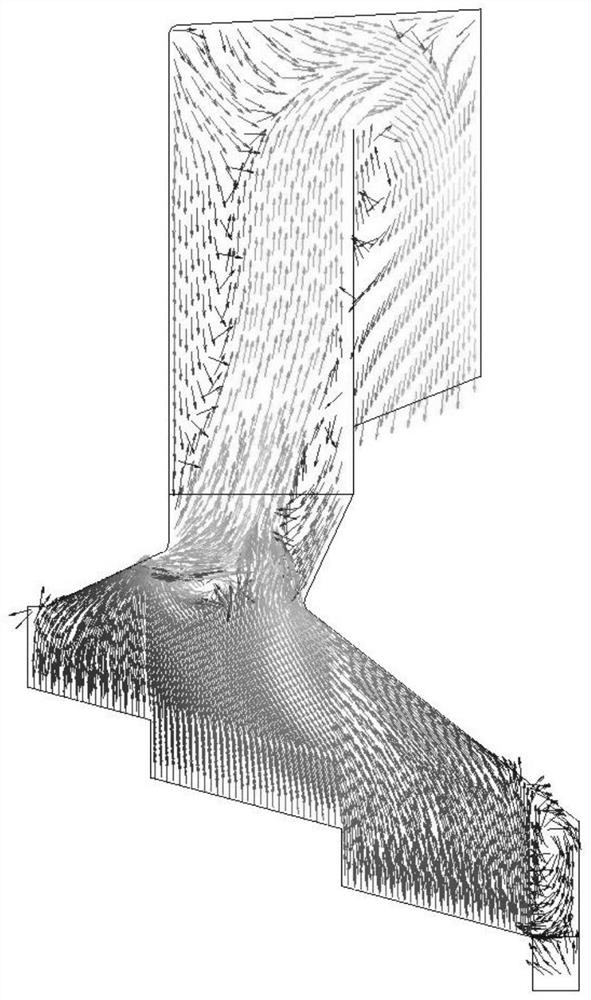
[0063] The flue gas flow field in the water wall area of ​​the waste incineration boiler in embodiment 1 is simulated, and the results are as follows image 3 as shown, image 3 It is the vector diagram of the flue gas flow field in the water wall area of ​​the waste incineration boiler provided by the embodiment of the present invention. pass image 3 It can be clearly seen that the erosion of flue gas on the ceiling of the first flue, the ceiling of the second flue and the back wall of the second flue is the most serious.

[0064] According to the simulation results of the above-mentioned flue gas flow field, for the upper part of the first flue, the ceiling of the first flue, the ceiling of the second flue, the area where the smoke temperature of the side wall of the second flue is higher than 750 ° C, and the area where the smoke temperature of the front wall of the second flue is higher than 750 ° C For the anticorrosion layer on the heating surface in the area where th...


PUM

PropertyMeasurementUnit
thicknessaaaaaaaaaa
thicknessaaaaaaaaaa
thicknessaaaaaaaaaa

Abstract

The invention belongs to the technical field of boiler corrosion prevention, and particularly relates to a corrosion prevention arrangement structure and method of a heating surface of a waste incineration boiler. The corrosion prevention arrangement structure provided by the invention comprises a fire-resistant pouring anti-corrosion layer arranged on a lower heating surface of a first flue, NiCrMoNb alloy surfacing anti-corrosion layers arranged on the heating surface of the upper part of the first flue and the heating surface of the area, with the smoke temperature higher than 750 DEG C, of the side wall of a second flue, NiCrMoW alloy and/or NiBSiMo alloy laser cladding anti-corrosion layers arranged on the heating surfaces of ceilings of the first flue and the second flue and the heating surface of the area, with the smoke temperature higher than 750 DEG C, of the rear wall of the second flue, and AN NiBSiCr alloy micro fusion welding anti-corrosion layer arranged on the heating surface of the area, with the smoke temperature higher than 750 DEG C, of the front wall of the second flue. According to the technical scheme provided by the invention, the problems that due to the fact that an existing high-parameter boiler adopts a single surfacing anti-corrosion layer form, excessive corrosion prevention exists in a part of areas, and the corrosion prevention effect of the part of areas is poor can be effectively solved, and economical and effective corrosion prevention arrangement is achieved.

Description

technical field [0001] The invention belongs to the technical field of boiler anticorrosion, and in particular relates to an anticorrosion arrangement structure and an arrangement method of a heating surface of a garbage incineration boiler. Background technique [0002] In order to increase the efficiency of waste incineration power generation, improving the main steam parameters of the waste heat boiler is the mainstream method. At the same time, the classification of waste and the improvement of living standards have gradually increased the calorific value of waste into the furnace, providing a basis for high-parameter power generation. The nickel-based alloy anti-corrosion layer on the heating surface is a standard configuration for high-parameter waste incineration boilers to alleviate high-temperature corrosion problems caused by harmful elements such as chlorine, sulfur, and alkali metals in waste. [0003] At present, all the nickel-based alloy anti-corrosion coating...

Claims


Application Information

Patent Timeline
Patent Type & Authority Applications(China)
IPC IPC(8): F23G7/00F23G5/44F23J11/00
CPCF23G7/00F23G5/44F23J11/00
Inventor 龙吉生刘亚成杜海亮曹阳白力高峰许绍进沈咏烈李桐王延涛
Owner SHANGHAI SUS ENVIRONMENT
Why Eureka
Try Eureka