Check patentability & draft patents in minutes with Patsnap Eureka AI!

Dynamic light-emitting tail lamp of automobile

A dynamic, automotive technology, applied to the semiconductor devices of light-emitting elements, light sources, motor vehicles, etc., can solve the problems of unfavorable promotion and application, inconvenient production and manufacturing, large volume, etc., achieving good three-dimensional texture effect, uniform and full light transmission Effect

Active Publication Date: 2021-01-26
ZHEJIANG JINYE AUTO PARTS CO LTD
View PDF8 Cites 0 Cited by
  • Summary
  • Abstract
  • Description
  • Claims
  • Application Information

AI Technical Summary

Problems solved by technology

[0002]At present, for the setting of the taillights on the car, it is necessary to specially set the turn signal and the position light, so the lamp assembly of the taillight is large in size and complex in structure. It makes the production quite inconvenient. At the same time, some existing textured car taillights generally have a plane texture on the outer light-transmitting plate of the lamp, which is not very obvious for the texture of the car lamp, and the effect is poor. The shape of the individual position lights inside the light-transmitting panel of the car light assembly is specially made, so that the position lights of the car light assembly can be seen from the outside after the lights have a certain texture. However, this method makes the structure of the car light assembly more complicated. Moreover, the manufacturing cost is relatively high, which is not conducive to popularization and application

Method used


Image

  • Dynamic light-emitting tail lamp of automobile
  • Dynamic light-emitting tail lamp of automobile
  • Dynamic light-emitting tail lamp of automobile

Examples


Embodiment 1

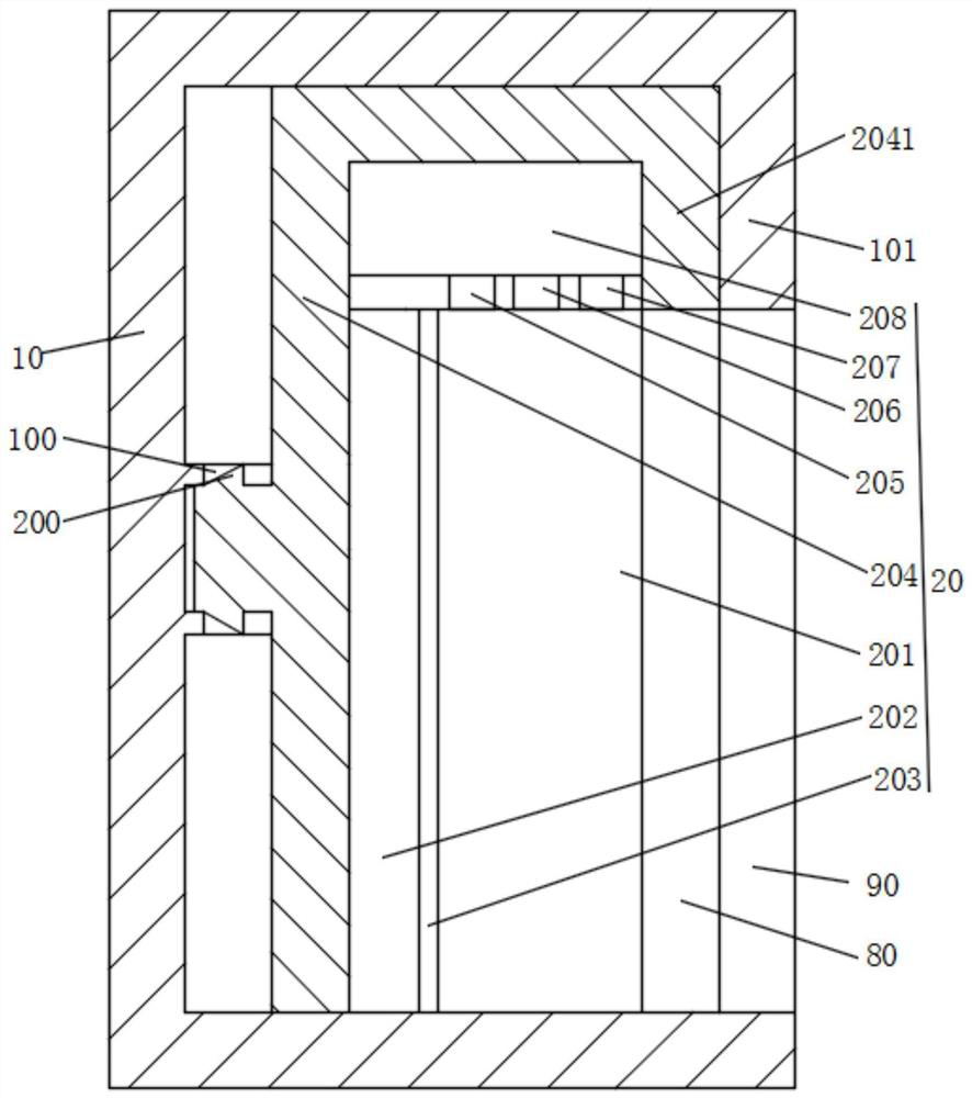
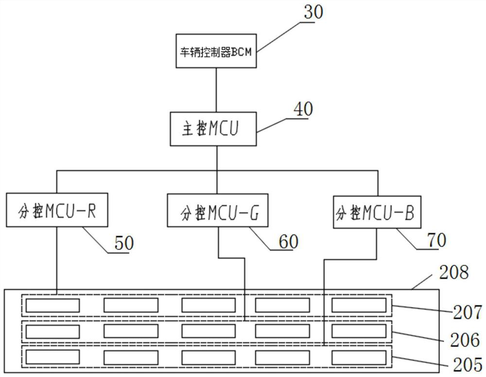
[0026] like figure 1 As shown, a kind of automobile dynamic luminous tail light described in this embodiment includes a strip-shaped lamp holder housing 10, and a surface light source lamp 20 arranged on the strip-shaped lamp holder housing 10, an inner lens 80, and an outer red The light-transmitting plate 90 and the control module 208 that controls the bright yellow light 20 or white light of the surface light source lamp, and the inner lens 80 is provided with a three-dimensional texture; the surface light source lamp 20 includes an optical resin transparent light guide plate 201 and is arranged on the optical resin transparent light guide plate 210 The top LED lamp board; the back side of the optical resin transparent light guide plate 21 is attached with a reflective film 203, and its front faces the red light-transmitting board 90; the LED lamp board is arranged with a green LED light-emitting chipset 205 connected to the control module, The blue LED light-emitting chips...

Embodiment 2

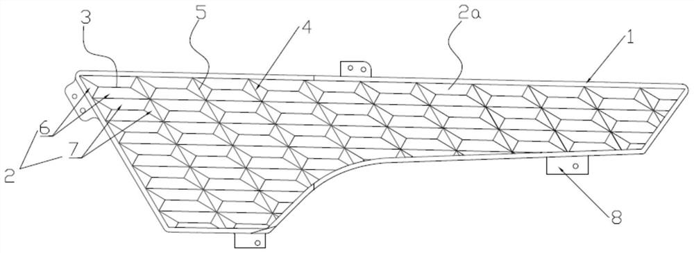
[0034] A kind of automobile dynamic luminous tail light described in this embodiment, its structure is consistent with embodiment 1, but only difference with embodiment 1 is that the inner light-transmitting mirror includes the inner light-transmitting mirror main body 1, and the inner light-transmitting mirror main body 1 is provided with There are a plurality of refraction parts 2, and the refraction parts 2 are connected into a prism-shaped convex structure 3 by several slopes 2a. A boundary line 4 , a depression 5 is formed between two adjacent refraction portions 2 that share the boundary line 4 . Each refraction portion 2 includes a light-transmitting area 6 and a shielding area 7, and the light-transmitting area 6 or the shielding area 7 is composed of at least one slope 2a respectively, wherein the refraction portion, slope, and prism-shaped protrusions arranged on the surface of the inner light-transmitting mirror body Structures, boundary lines and depressions consti...


PUM


Abstract

The invention discloses a dynamic light-emitting tail lamp of an automobile. Three-dimensional textures are arranged on an inner lens; a face light source lamp comprises an optical resin transparent light guide plate and an LED lamp panel arranged at the top of the optical resin transparent light guide plate. The back surface of the optical resin transparent light guide plate is attached to the reflecting film, and the front surface faces the outer red light-transmitting plate; a green LED light-emitting chip set, a blue LED light-emitting chip set and a red LED light-emitting chip set which are connected with the control module are arranged on an LED lamp panel, and the green LED light-emitting chip set, the blue LED light-emitting chip set and the red LED light-emitting chip set in eachrow are arranged in the length direction of the optical resin transparent light guide plate. By means of the structure, the position lamp and the steering lamp can be lightened in the automobile lampassembly, the automobile tail lamp with the steering lamp and the position lamp can be achieved only through one red light-sharing plate, light emitted through the area light source is more uniform and full, the three-dimensional texture effect displayed after the inner light-transmitting mirror is lightened is better, and the automobile tail lamp is more attractive and relatively enriched.

Description

technical field [0001] The invention relates to the technical field of an automobile tail light device, in particular to an automobile dynamic luminous tail light. Background technique [0002] At present, the setting of taillights on automobiles requires special setting of turn signals and position lights, so the lamp assembly of taillights has a large and complex structure, which makes production quite inconvenient. At the same time, some existing textured automobile taillights , this kind of tail light is generally provided with a plane texture on the outer light-transmitting plate of the lamp, which is not very obvious for the texture of the car light, and the effect is poor, or the shape of the light at a separate position in the outer light-transmitting plate of the car light assembly It is specially made so that the position light of the car light assembly can be seen from the outside after the light is turned on to have a certain texture. However, this method makes t...

Claims


Application Information

Patent Timeline
Patent Type & Authority Applications(China)
IPC IPC(8): F21S43/14F21S43/20F21S43/235F21S43/50F21V23/00F21V17/16F21W107/10F21Y115/10
CPCF21S43/14F21S43/20F21S43/235F21S43/50F21V23/00F21V17/16F21W2107/10F21Y2115/10
Inventor 蒋斌斌刘子豪张成
Owner ZHEJIANG JINYE AUTO PARTS CO LTD
Features
  • R&D
  • Intellectual Property
  • Life Sciences
  • Materials
  • Tech Scout
  • Unparalleled Data Quality
  • Higher Quality Content
  • 60% Fewer Hallucinations
Learn More