Passive residual heat removal heat pipe heat exchange system for spent fuel pool

A spent fuel pool, passive waste heat technology, applied in indirect heat exchangers, nuclear power generation, lighting and heating equipment, etc., can solve problems such as dry burning of evaporation tubes, achieve equal pipeline resistance, overcome the increase in saturation temperature, and have Conducive to the effect of uniform distribution of steam flow

Pending Publication Date: 2021-02-02
BEIJING UNIV OF CHEM TECH
View PDF1 Cites 0 Cited by
  • Summary
  • Abstract
  • Description
  • Claims
  • Application Information

AI Technical Summary

Problems solved by technology

However, in this patent, the top of the upper header of the evaporator is connected to the gas riser pipe, and the side lower part of the lower header is connected to the liquid downcomer. Due to the influence of the static pressure of the liquid column on the evaporation temperature, the evaporation pipe above the free liquid surface The unfavorable situation of dry burning on the wall

Method used


Image

  • Passive residual heat removal heat pipe heat exchange system for spent fuel pool
  • Passive residual heat removal heat pipe heat exchange system for spent fuel pool
  • Passive residual heat removal heat pipe heat exchange system for spent fuel pool

Examples


Embodiment 1

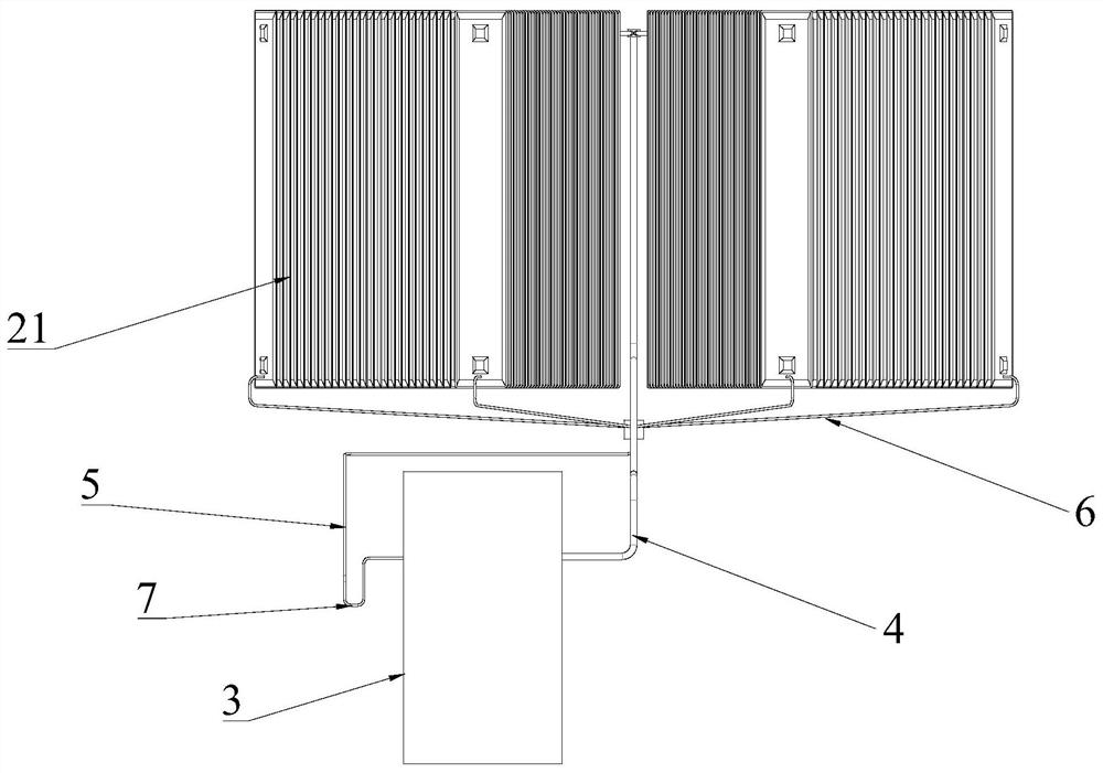
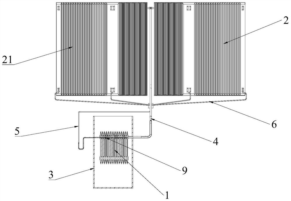
[0077] Such as Figure 1 to Figure 10 As shown, this embodiment provides a spent fuel pool passive waste heat export heat pipe heat exchange system, the system includes an evaporator 1 and a condenser 2, the evaporator 1 is immersed in the water of the spent fuel pool 3; the condenser 2 is set in the spent fuel pool Outside the fuel pool 3, the condenser 2 includes several condensing units 21, which are arranged in parallel; the evaporator 1 and the condenser 2 are connected through the steam main pipe 4 and the condensate main pipe 5, forming a closed circulation heat pipe heat exchange circuit; Both the steam header 4 and the condensate header 5 communicate with the upper part of the evaporator 1 .

[0078] Specifically, such as Figure 4 with Figure 5 As shown, the evaporator 1 includes a plurality of sequentially connected evaporating sheets 11 , the evaporating sheets 11 are stamped and formed by a 1 mm thick stainless steel plate, and then the inner and outer edges ar...

Embodiment 2

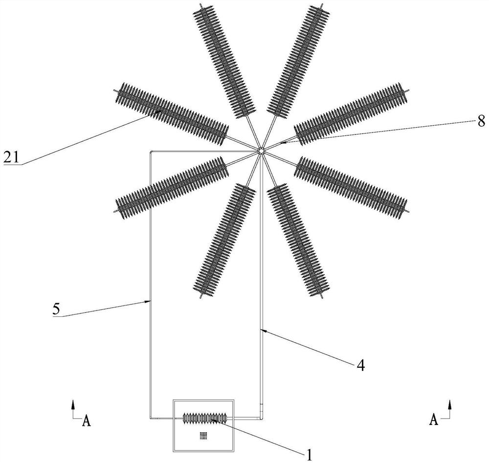
[0085] Such as figure 1 with figure 2 As shown, this embodiment is a further supplement to Embodiment 1. Several condensing units 21 are radially dispersed and arranged in parallel. A cold end condenser 2 heat transfer performance.

[0086] Preferably, the condensate collection pipe 6 has a downward slope between the condensate flow direction and the horizontal plane, and several condensate collection pipes 6 are distributed radially on a conical surface; it is beneficial to the collection of condensate, as the most preferred embodiment of this embodiment Preferably, the slope is not less than 10°; the collecting pipe of the condenser 2 is connected with the condensate main pipe 5 through the condensate collecting pipe;

[0087] Further, several steam distribution pipes 8 are distributed radially, on a horizontal plane or on the same conical surface. Since the steam distribution pipe 8 is located in the radial center, the temperature is higher, so the pressure in the radial ...

Embodiment 3

[0089] Such as Figure 10 As shown, the difference between the present embodiment and the second embodiment is that several condensing units 21 are arranged in parallel;

[0090] Preferably, the condensate collecting pipes 6 are arranged in parallel and vertically, and are sequentially collected and communicated with the condensate main pipe 5;

[0091] Preferably, the steam distribution pipes 8 are arranged in parallel.

[0092] Specifically, if the layout space of the condenser 2 is limited, the condensing units 21 can also be arranged in parallel and in parallel, that is, the condensing units 21 are arranged in parallel with each other at a certain interval, and each steam distribution pipe 8 is perpendicular to the steam main pipe 4, and the steam enters each steam pipe from the main pipe in turn. Steam distribution pipe 8. The condensing units 21 are arranged in parallel and in parallel. This arrangement is compact and regular, and is suitable for the condition of limit...


PUM


Abstract

The invention discloses a passive residual heat removal heat pipe heat exchange system of a spent fuel pool. The system comprises an evaporator immersed in water of a spent fuel pool, and a condenserarranged outside the spent fuel pool and comprising a plurality of condensation units arranged in parallel. The evaporator is communicated with the condenser through a steam header pipe and a condensate header pipe to form a closed circulating heat pipe heat exchange loop. The steam header pipe and the condensate header pipe are both communicated with the upper portion of the evaporator. Accordingto the passive residual heat removal heat pipe heat exchange system for the spent fuel pool, a falling film evaporation method is adopted, dry burning of the evaporator can be avoided, the condenseris arranged in a radial mode, and the heat exchange efficiency is improved.

Description

technical field [0001] The invention belongs to the technical field of spent fuel pool cooling in nuclear power plants, and in particular relates to a passive waste heat export heat pipe heat exchange system for spent fuel pools. Background technique [0002] At present, in advanced pressurized water reactor nuclear power plants, the spent fuel still has a large residual decay power after it is unloaded from the nuclear reactor core, and is temporarily stored in the spent fuel storage pool for cooling. Exported and isolated from radioactivity by water. [0003] The cooling system of the spent fuel pool of nuclear power plants is an active cooling system. The high-temperature water flow in the spent fuel pool is pumped out by an electric pump, cooled by a heat exchanger, and then transported back to the spent fuel pool for heat exchange. The pumps are powered by an off-site power source, and in the event of loss of the off-site power source, are powered by emergency diesel g...

Claims


Application Information

Patent Timeline
IPC IPC(8): G21C15/18F28D15/02
CPCF28D15/0266G21C15/18Y02E30/30
Inventor 卢涛陈学罗彦
Owner BEIJING UNIV OF CHEM TECH
Why Eureka
Try Eureka