
ENT surgery cleaning equipment
A cleaning equipment and ENT technology, which is applied in the field of ENT, can solve the problems of not being able to meet the needs of medical staff, reduce the practicality of the appliance cleaning device, and poor cleaning effect, so as to increase the sterilization effect and solve the problem of poor sterilization effect , the effect of saving the time used
- Summary
- Abstract
- Description
- Claims
- Application Information
AI Technical Summary
Problems solved by technology
Method used
Image

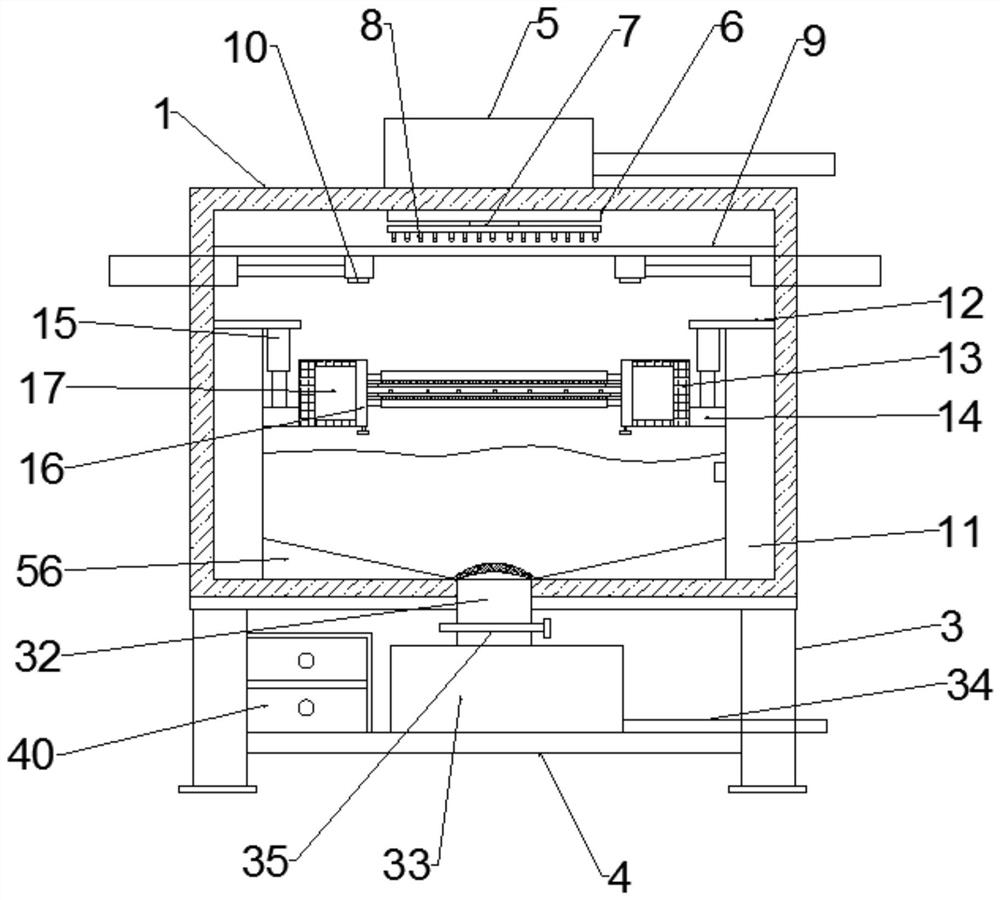
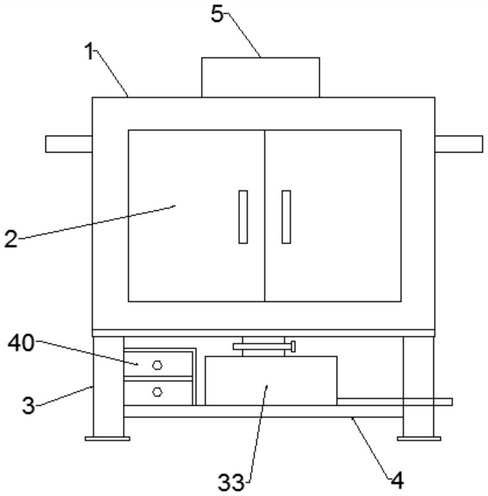
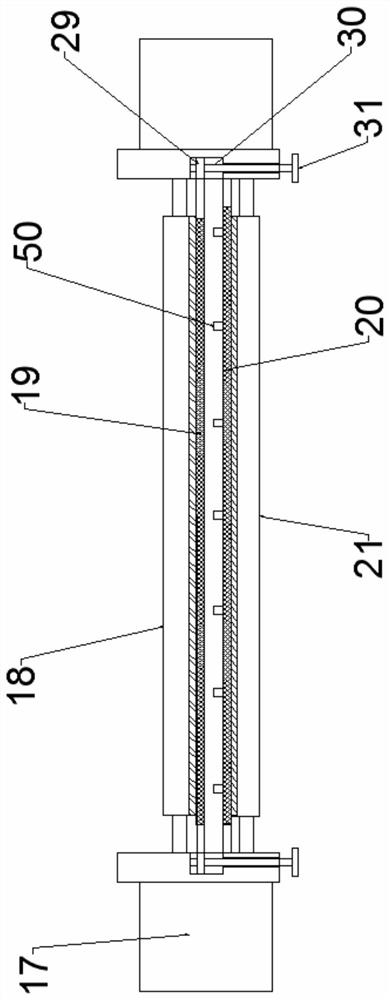
Examples
Embodiment 1
[0030] Embodiment one: if Figure 1-8 As shown, a material box 40 is arranged on one side of the upper end of the horizontal plate 4, and a plurality of drawer boxes are arranged on the material box 40, and the front ends of the drawer boxes are all provided with handles. The sliding device 9 includes a supporting plate 41 at the middle part of the upper end of the box body 1 and located below the water spray connector 7. Both sides of the lower end of the supporting plate 41 are provided with receiving plates 42. The lower end of plate 42 is all provided with slide rail 43, and the two ends of described receiving plate 42 are all provided with the slide block 44 that cooperates with described slide rail 43, is connected with support plate 2 45 between the lower end of described slide block 44. The middle part of the lower end of the support plate 2 45 is connected to the ultraviolet germicidal lamp 10 , and the two ends of the box 1 are provided with electric telescopic rods ...
Embodiment 2
[0031] Embodiment two: if Figure 1-8 As shown, the movable rod 1 24 and the movable rod 2 25 are both provided with a limit block 47 at the inner top of the fixed frame 13 , and a rubber plate is provided on one side of the inner wall of the fixed frame 13 . Described connecting net plate one 19 and described connecting net plate two 20 all comprise connecting frame 48, and the middle part of described connecting frame 48 is all provided with opening, and the middle part of both ends of described connecting frame 48 is all connected with described threaded hole block. 29 is fixedly connected, the middle opening of the connecting frame 48 is provided with a limiting net 49, one end of the limiting net 49 is connected to the connecting frame 48 through a hinge, and the other end of the limiting net 49 is connected to the connecting frame 49. The frames 48 are connected by fixed locks. The limiting net 49 of the connecting net plate 20 is provided with a number of silica gel li...
Embodiment 3
[0032] Embodiment three: as Figure 1-8 As shown, the movable brush plate one 18 and the movable brush plate two 21 all include a movable frame 52, and both ends of the movable frame 52 are connected with the movable rod one 24 and the movable rod two 25 Matching connection, the middle part of the movable frame 52 is provided with a connection port, the middle connection port of the movable frame 52 is provided with a dust removal brush plate 53, and the upper end of the dust removal brush plate 53 is provided with a number of water inlet holes 54 , Both ends of the dust removal brush plate 53 are connected to the movable frame 52 through connecting locks. Both ends of the dust removal brush plate 53 are provided with two handles 55 in the middle. The lower end of the fixed water tank 11 close to the bottom end of the outlet pipe 32 is provided with a sloping plate 56 , and the slanting plate 56 is integrally connected with the fixed water tank 11 . The bottom end of the sup...
PUM
 Abstract
Description
Claims
Application Information