Supporting structure of horizontal stirring tank and horizontal stirring tank

A supporting structure and mixing tank technology, applied in the field of supporting structures, can solve problems such as material jamming, achieve the effects of reducing blocking, enhancing fluidity, and preventing jamming and sagging

CN112546895APending Publication Date: 2021-03-26CHONGQING CHANGZHENG HEAVY IND
0 Cites 1 Cited by

Patent Information

Authority / Receiving Office
CN · China
Patent Type
Applications(China)
Current Assignee / Owner
Publication Date
2021-03-26

Smart Images

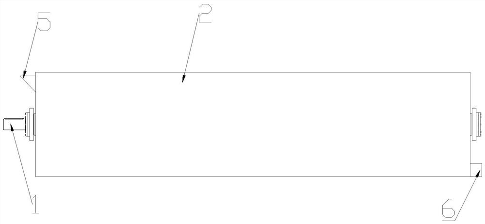
  • Figure 1
    Figure 1
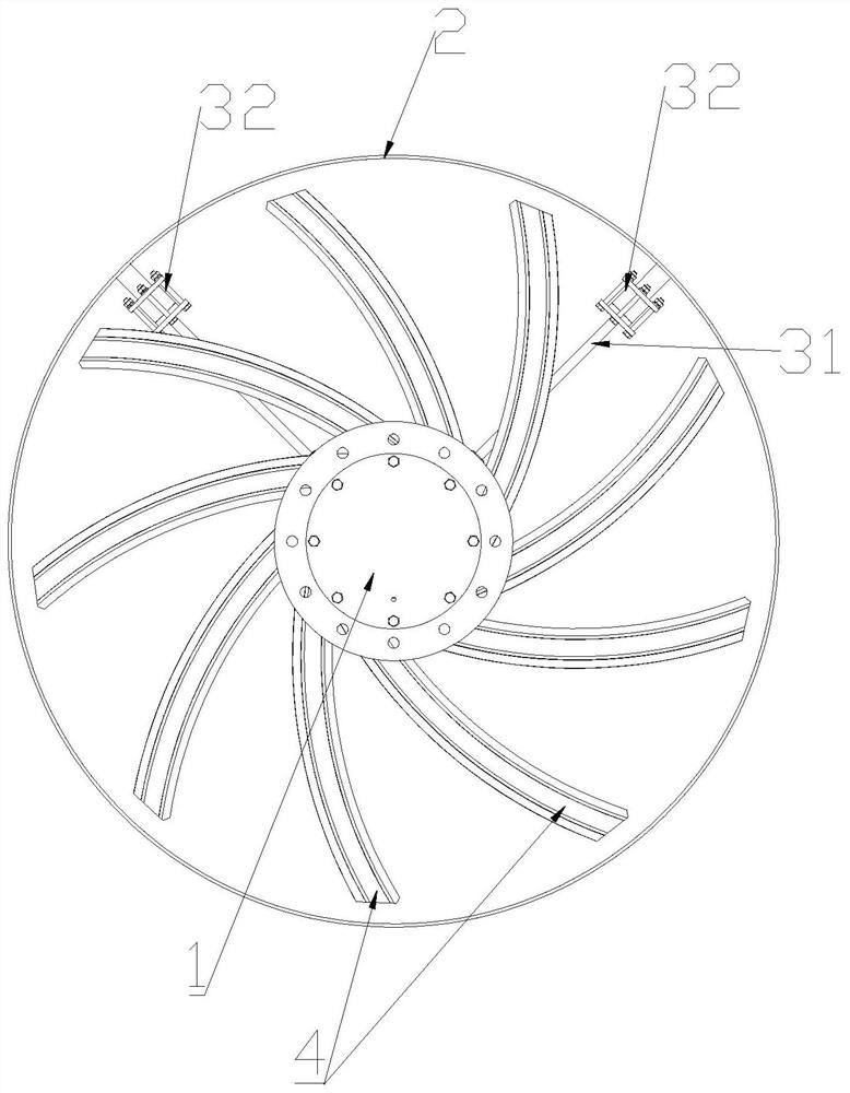
  • Figure 2
    Figure 2
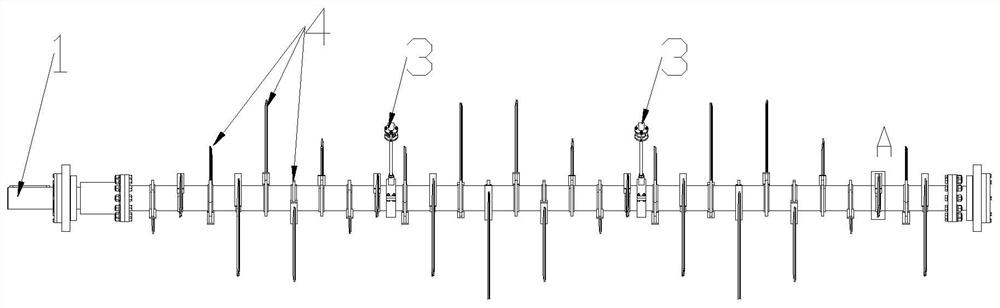
  • Figure 3
    Figure 3
Patent Text Reader

Abstract

The invention discloses a supporting structure of a horizontal stirring tank and the horizontal stirring tank. The supporting structure of the horizontal stirring tank comprises a transversely-arranged tank body and a stirring shaft arranged in the tank body, the stirring shaft is sleeved with a supporting component, a connecting rod extends out of the supporting component, and the free end of theconnecting rod is fixedly connected with the inner wall of the upper half portion of the tank body; and the connecting rod is a bendable and telescopic elastic piece. According to the invention, theconnecting rod of the supporting component is positioned at the upper half part of the tank body, so that the blockage of materials at the lower half part of the tank body is reduced, and the flowability of materials in the tank body is enhanced; the connecting rod is the elastic piece, when the materials in the tank body are unevenly paved or the stirring shaft is extruded by the materials to deform, the whole stirring shaft adjusts the position of the stirring shaft according to the state of the materials, the connecting rod provides a force for returning to the original position for the deformed stirring shaft, and continuous rotation of the stirring shaft is guaranteed. Materials can be favourably and smoothly pushed into the tank body, and the stirring shaft is effectively prevented from being blocked and drooping.
Need to check novelty before this filing date? Find Prior Art

Description

technical field

[0001] The invention relates to a supporting structure, in particular to a supporting structure of a horizontal stirring tank and the horizontal stirring tank. Background technique

[0002] The horizontal stirring tank is mainly used for the treatment of biomass organic waste such as dry anaerobic fermentation or dry aerobic organic fertilizer reaction. The length of the traditional large-scale horizontal fermentation digester or reactor tank is usually greater than 30m. Due to the winding of the internal stirring shaft, it is necessary to apply bottom support components in a suitable area to offset the sagging of the stirring shaft. The supporting parts will form a barrier in the lower part of the tank, affecting the flow of materials in the tank; especially when the solid content of the mixed material in the tank reaches more than 25%, the material itself has no fluidity, and the supporting parts will cause the material in the tank to flow. There is a phen...

Examples

Embodiment Construction

[0031] It should be noted that, unless otherwise specified, all technical and scientific terms used in this application have the same meaning as commonly understood by those of ordinary skill in the art to which this application belongs.

[0032] In order to make the object, technical solution and advantages of the present invention clearer, the present invention will be further described in detail below in conjunction with the accompanying drawings and embodiments. It should be understood that the specific embodiments described here are only used to explain the present invention, not to limit the present invention.

[0033] like figure 1 and figure 2 , a support structure of a horizontal stirring tank, comprising a horizontally arranged tank body 2 and a stirring shaft 1 arranged in the tank body 2, a supporting part 3 is set on the stirring shaft 1, and a connecting rod protrudes from the supporting part 3 31, the free end of the connecting rod 31 is fixedly connected wit...